|
<< Click to Display Table of Contents >> Shadings 3D calculation |
  
|
|
<< Click to Display Table of Contents >> Shadings 3D calculation |
|
This is a pedagogic tool, which shows an animation of the shadings on your system, during any chosen day (under clear sky conditions). This tool is only informative, not necessary to the execution of the simulation.
When the Module Layout system is fully defined, ready for simulation, you can open this page:
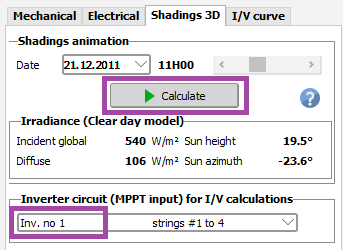
Clicking on "Calculate" will initiate an animation of the shadings on the tables corresponding to the selected inverter, for any chosen day.
Then you can use the scrollbar to view the result for any quarter of hour.
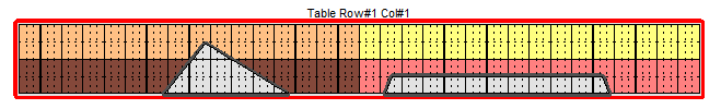
This example shows a shade on a table with Twin half-cut cells modules in portrait.
Right-clicking on a semi-shaded module (or any module) will show the electrical behaviour of the I/V curves: in this case (13th module from left):
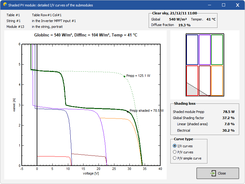
This shows the special behaviour of a twin- half-cells modules:
| - | The first submodule (bottom left, red) is partially shaded: the I/V curve corresponds to the diffuse. |
| - | The second submodule (top left, blue) is not shaded: its full current has to be added to the current of the first one. |
| - | The center submodules (brown and violet) are in the same situation, their currents are added and lead to the same I/V curve. |
| - | The voltages of both I/V curves (identical in this case) have to be added (braun and violet curves). |
| - | Finally the right submodules (orange and green) are not shaded, their own I/V curve is a usual full-current curve. However when adding the voltages to the preceding sub-modules, this leads to the resultant curve in green/black. This is not so apparent, but you can check that for each current value, the resultant voltage corresponds to the sum of the previous curves (braun and violet) and a "normal" I/V curve. |
NB: You can see these behaviours as P/V curves also. The interpretation is less evident ...
The resultant is the real I/V curve of the module (Pmpp shaded, here = 78.5 W).
Now the total shading loss is the ratio of this Pmpp shaded to the Pmpp of the unshaded module (125.1 W), i.e. 37.2%.
In this case the "Linear" shading loss (ratio of the shaded area applied to the beam component, i.e. the deficit in irradiance) is 7 %.
Therefore the electrical loss factor (due to the I/V mismatch) is the difference Pmpp shaded - PshdLin = 37.2% - 7.0 %.