|
<< Click to Display Table of Contents >> Module Layout: Calculation in the simulation |
  
|
|
<< Click to Display Table of Contents >> Module Layout: Calculation in the simulation |
|
The Module Layout construction defines the exact localization of each PV module in the 3D scene, and its electrical attribution to a given string in the system. The objective of the calculation within the simulation is to determine an electrical shading factor to be applied to the Beam component.
Calculation by MPPT input
During the simulation, the Module Layout calculation has to be performed at each time step, for each MPPT input, i.e. for each "electrical sub-array" (set of strings connected in parallel) independently.
The basic data is the shade polygon calculated by the 3D scene on each table. This shade is distributed on each sub-module, and determines the "linear" shading factor for this sub-module, as well as its electrical I/V curve.
We can observe that the I/V curve of a shaded sub-module is quasi-identical, whatever the number of shaded cells within the sub-module. This is due to the fact that the current is driven by the less irradiated cell, so that the I/V curve of the sub-module is essentially the remaining production of the diffuse. Therefore the sub-module is the natural "unit" when calculating the I/V curve of a module or array.
I/V curve calculation
In a first step, the sub-modules I/V curves of each string are added in voltage (i.e. Voltages of NS shaded submodules + Voltage of NU unshaded sub-modules for each current value). This gives a resultant I/V curve for the string.
In a second step, the Currents of each string in parallel are added, leading to the resultant I/V curve of the full electrical sub-array.
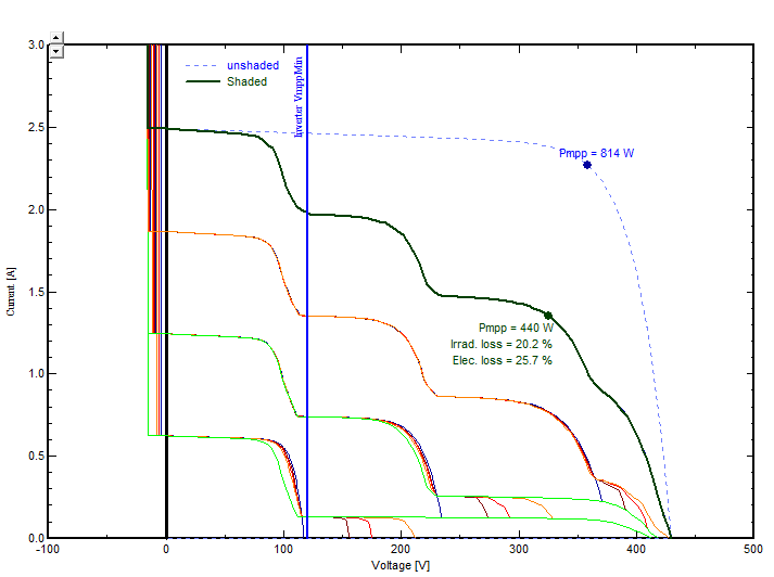
On this resultant curve, the inverter (MPPT) will "choose" the voltage corresponding to the Maximum Power Point. This will define the effective Shaded power PShaded.
NB: in some cases the maximum voltage corresponding to PShaded may be below the minimum voltage of the Inverter MPPT range (VmppMin). In this case PVsyst will choose the best value between the secondary MPP (corresponding to the diffuse) and the Power at VmppMin.
Electrical Shading Factor
The global shading loss is Pmpp (of undisturbed array) - PShaded.
Now the shading loss is splitted into a "linear" shading loss contribution, evaluated from the geometrical shades on each sub-module, and the "Electrical" shading loss.
Therefore the final Electrical loss is PElec = Pmpp - PShaded - PLinear.
The shading factor on the beam component is finally PElec / (Pmpp * FracBeam), where FracBeam = Beam/Global irradiances.
Example
The graph below gives an example of a shaded sub-array of 4 strings. On the bottom string, 2/3 of sub-modules are shaded.
This kind of curves is available in the "Module layout" construction part, page "I/V curve", for clear sky conditions.It is not available during the simulation.