|
<< Click to Display Table of Contents >> PV module - Rshunt exponential behavior vs Irradiance |
  
|
|
<< Click to Display Table of Contents >> PV module - Rshunt exponential behavior vs Irradiance |
  
|
The shunt resistance Rshunt - corresponding to the inverse of the slope of the I/V curve around V=0 - is considered as a constant parameter in the standard one-diode model.
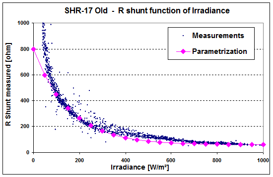
But when performing I/V curves measurements at different irradiances, we observe that this measured RShunt value increases when the irradiance diminishes. This is valid for any PV cells technology, but it is especially visible with amorphous I/V curve families, where the Rshunt is very low (i.e. the I/V slope around Isc is important).
The next figure shows our measured Rshunt behaviour for one of our long-term measurements, for an amorphous module.

This distribution may be approximated by the following exponential expression:
Rshunt(eff) = RshB + [ Rsh(0) - RshB ] · exp( -Rshexp · (G / Gref) )
RshB is an auxiliary parameter for this expression, ensuring that the curve "Rshunt(eff)" passes indeed by the Rshunt value at 1000 W/m2. This is calculated by putting RShunt(Eff) = Rshunt in the above equation.
We observed a similar behaviour on all our measured data (including the Si-Crystalline and CIS modules). And curiously, all data may be rather well approached using a unique value Rshexp = 5.5 (except the CdTe module where it should be around 3). Therefore this value is set as default value in PVsyst.
In this expression there are 2 unknown parameter: Rshunt of the standard model at STC, and Rsh(0), the intercept at G = 0. These parameters may be determined on measured data, but are not available in the usual manufacturer's data sheets.
We have seen that when establishing the model at STC, in absence of an I/V curve measurement we choose a default value Rshunt = Vmpp / (0.2 * (Isc - Impp)).
According to our outdoor long term measurements on several modules:
➢For amorphous modules, we observed a ratio of Rsh(0) / RShunt = 12, which is very similar for all measured modules, including CdTe. This exponential correction is extremely important in the model, as the RShunt is low, so its weight in the model is high.
➢For Si-crystalline and CIS, we observed a rather stable ratio of around Rsh(0) / RShunt = 4 , but this is more difficult to establish as the Rshunt of crystalline modules is high, so that the slope is very low and difficult to measure with accuracy.
With the measured low-light flash-test data that we have received from many manufacturers, we can estimate this ratio to be rather 8 to 10. However the exact ratio has a very low impact on the final model, because Rshunt is already very high at STC, so that its influence is negligible for higher values under low-light irradiance. Moreover, its influence is taken into account when adjusting the RSerie for a required low-light performance.
NB: When several Rshunt values are available for different irradiances, PVsyst provides a tool for adjusting the corresponding Rsh(Gref) and Rsh(0) parameters.
Back to Standard "One-diode" model.
Back to Amorphous and Thin films modules.