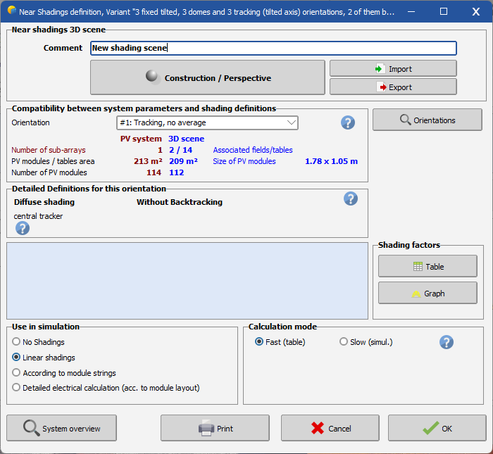
Near Shadings: Main dialog
The "Near shadings" dialog is the Dashboard for near shadings treatment.
You have to begin with the button Construction/Perspective, which opens the 3D editor for building the global scene.
When exiting this tool with a valid 3D shading scene, the program will check the compatibility of your construction with elements previously defined for your system:
- The orientation of your 3D fields should match the one defined on the "Orientation" part. If it is not the case the program will ask whether you want to update the "Orientation" definitions.
- You should have defined sufficient and reasonable 3D area for putting the modules defined in the "System" part.
Therefore this implies that you have already defined (roughly) the main parameters of the system. This will be the case if you follow the advice of building your whole PV system "step by step", beginning with the most simple configuration without any complications, saving this version and adding complexities one after the other.
Table of shading factors
Once this scene has been well established, the Table button allows you to construct the shading factor table, which computes the Shading factor for a grid of sun (space) directions.
This process also calculates the diffuse and albedo attenuation factors, constant over the year.
After that you will be able to see the Iso-shading diagram and run the simulation.
If you have defined a partition in module strings during your 3D construction, two tables will be calculated simultaneously: one for the conventional "irradiance" or "linear" shading factor, and one for the shading factor according to the module strings.
Use in simulation
Now you have to specify how you want to take the shadings into account during the simulation. You have several choices depending on your progress in the system's study, the size of your system, etc.
- Linear (irradiance) shadings will only take the deficit of irradiance on the PV field into account, without electrical effect. This represents a lower limit of the full shading losses.
- You can compute this simulation either in a fast way (interpolating in the shading factor table at each step), or in a slower way by computing the full shading factor at each simulation step.
- According to module strings: during the construction of the 3D scene, you can define a partition in module strings. This option will calculate a shading factor "According to strings", representing a higher limit for electrical effects.
- For a final result you can specify the Fraction for electrical effect, which is a cursor between pure "linear" calculation (lower limit 0%) and full electrical effect (higher limit 100%).
- Detailed, according to Module Layout: Finally, after specifying a detailed "Module layout" configuration, you can ask to compute the shadings according to detailed electrical losses.
Model Library
The shading scene parameters are stored with your "calculation version", and don't give rise to any additional files.
However, you can store your 3D shading scene in a *.SHD file, which may be reused in another project.
