Object positioning
Each shading object is built in it's own referential and then positioned in the global scene.
To position an object, use the ![]() button or the "Object -> Position in scene" menu item.
button or the "Object -> Position in scene" menu item.
The corresponding keyboard shortcut is Ctrl+B.
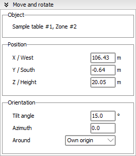
This will show the positioning dialog:
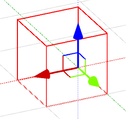
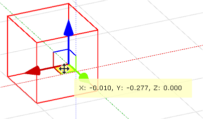
And it will also display the help tool for moving the object with the mouse directly in the scene:
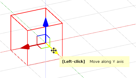
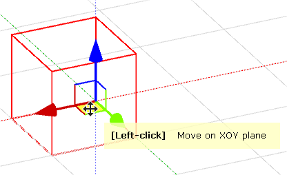
The help tool allows you to move the object on one or two axes as shown in the images below:
Moving an object on one axis:
Moving an object on two axes:
Left click and drag to move the object:
Positioning operations are greatly facilitated when using orthogonal views in order to drag the object more accurately in the scene.
From a mathematical point of view, parameters are defined in such a way that the object is first displaced in the main referential, then it is rotated by the given azimuth angle, and finally tilted around the new OX' rotated axis.
This process is the same for positioning an elementary object in a "building" object.
Fine tuning
You can also use the arrow keys to move the object in the scene on two axes, depending on the current selected view.
You must combine the arrow key with Ctrl, Shift or both in order to move the object.
When moving an object either with the mouse or the arrow keys :
- pressing Ctrl will move the object by 1 centimeter.
- pressing Shift will move the object by 10 centimeters.
- pressing Ctrl+Shift will move the object by 1 meter.
Important notice
When positioning PV planes among other objects, please always leave a little space between the plane and the support surface. Indeed, shading calculations involve complex calculations of intersections and reunions between 2D projections of these objects. Confused points (and also points confused with a surface) often cause problems to these routines, and may sometimes lead to topological errors.
On the other hand, module shading calculations consider a rectangle as shaded as soon as one point is shaded. When confused with its support surface, the baseline of the PV plane is calculated as shaded, and invalidates the lower rectangles.
