Partition in strings of modules
Basics of partitioning
The partitioning for the Electrical calculation is done in the window of each field/table definition in the 3D scene.
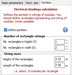
The gist of the procedure is as follows: on each table in the 3D scene, you have to define rectangles, called partitions, representing a group of PV cells that will cease to produce energy once partial shadings are sufficiently spread out on it. You can define these rectangles either by their number in height and length of the table, or by their sizes. A rectangle will generally either correspond to the height of one module, or to an integer fraction of the module height.
In the definition window (tab "partition" of the 3D field editor), the checkbox Define partition lets you specify whether you want to define partitions for this table. Next, you can define the number of partitions in height and width (or directly their size). The partitions will be separated by dotted lines on the PV table.
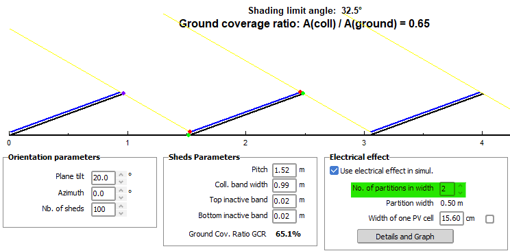
2D model ("unlimited" orientations)
When working on unlimited orientations, the principles of partitioning can also be applied to the electrical shading definitions. All the cases described in the summary table below should be treated in the same way.
Typical cases
Regular arrays, generalities
In regular fixed tilt arrays or arrays of trackers, to minimize the electrical losses you should ideally gather all the modules connected to the same MPPT input on a same row, on one or multiple tables. This will ensure that all modules on the MPPT input operate in the same partial shading conditions.
If letting all modules on a given MPPT input have the same shading conditions is not possible, cabling each string over 2 or more rows (sometimes called U-cabling) is a good alternative choice for modules in landscape orientation. In portrait orientation this type of cabling will not help (see below).
Systems with "little" tables
Many systems are now defined by little tables (of less than about 10 modules in width), often imported from other CAD software, and often positioned on hilly terrain.
In terms of partitioning, a string laid out over multiple tables will simply be represented by multiple partitions, as a partition is geometrically bounded to the table. One may worry that this would lead to problems with the simulation. However, this is not the case: if the tables are positioned in rows, side-by-side on the terrain, defining part of the string in each table will be effectively equivalent as defining a full string in a wide table. All the bottoms of the tables will be shaded at the same time, in the same way as for a much longer table with one or multiple strings in length.
Half-cut modules
For half-cut cells modules, the ideal is to put them in portrait. In this case you will define partitions that are half the height of the module. Note that U-cabling here is not a good choice, as it is not as resilient to partial shadings.
In landscape, half-cut modules will behave exactly like a normal module: there is no specific benefit for the electrical shading loss from the cell layout.
String inverters / All strings on a single MPPT are shaded in the same way
In the specific case of single-string inverters, or whenever all the strings (laid-out on one row) on a given MPPT input are shaded in the exact same way, modules in landscape orientation will suffer less from shadings than in the case of a central inverter. This is the case both for half-cut or standard cell modules (with three sub-modules in general). When shading the bottom row of cells, the loss of production will only be of about one third on clear-sky conditions, due to modules having three sub-modules in the height of the partition. Once all effects are taken into account, it was found that these strings are best modeled with two partitions per row of modules (see case 1L below).
String optimizers
When connected to string optimizers, whether or not multiple strings are put in parallel with each other on the same MPPT, these will usually behave as in the string inverter case (see above). For modules in landscape, strings on a single row, the best model is two partitions per row of modules.
Defining rectangles as one module / Module optimizers
Some people define each partition as one only module or only one sub-module. This is not the right way, except when you are using an optimizer on each module (sub-module).
If the optimizer acts on 2 modules in series, you should define partitions representing 2 modules.
Other cases
It is not always possible to define exactly one partition for one string. Some strings may have modules irregularly distributed on 2 rows. In some other cases, there is no contiguous and rectangular group of cells acting as a single partition that would turn on or off depending on the shadings.
Remember that this electrical calculation is only an approximation. The particular cases should be calculated using the Module Layout option. The module layout may also serve as a guide to define partitions. In the case of a very large system for example, you can consider a smaller version of the system to calculate the effects of shadings accurately with the module layout, and use these results to properly define the partitions.
Summary for common cases
To summarize the cases above, we identify the configuration of the strings in the following way: Number of rows - Orientation - (optional) U-cabling.
"Number of rows" (marked as an integer number) is the number of rows in the height of the table spanned by all the strings of a given MPPT input. By default we suppose that the strings are laid out on one row. U-cabling (marked as U) is for the case where the strings are laid out over multiple rows in the height of the table. Finally the Orientation may either be L (standard or half-cut modules in landscape), P (standard modules in portrait), or T (half-cut modules in portrait).
The following table describes the most common cases; click on the images to enlarge them. Note that x stands for any integer number, unless the case is explicitly stated (e.g. 1L).
| Case | #Partitions in height | Sketch | Partition definition |
|---|---|---|---|
| 1L | 2 | 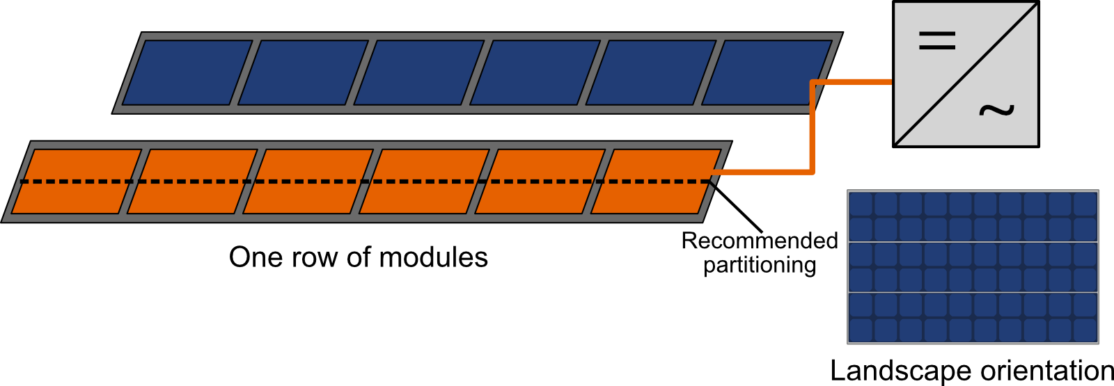 | 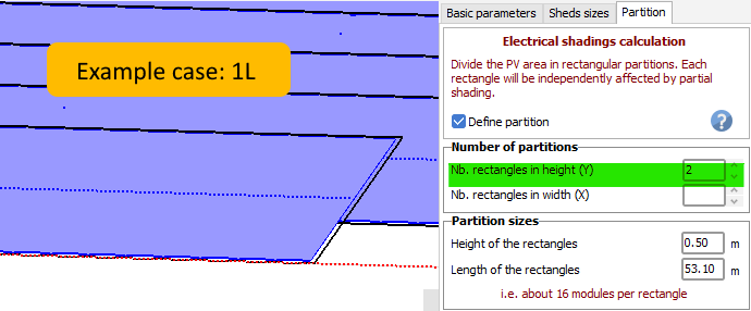 |
| xL | x | 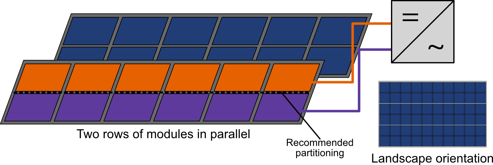 |  |
| xLU | x* | 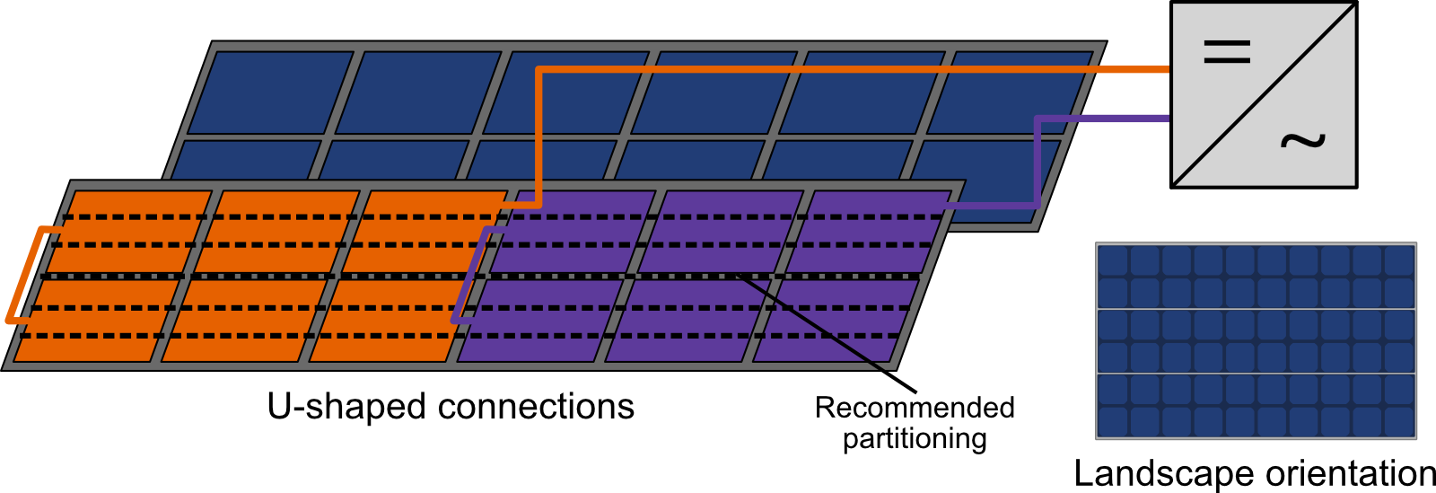 |  |
| xP | x | 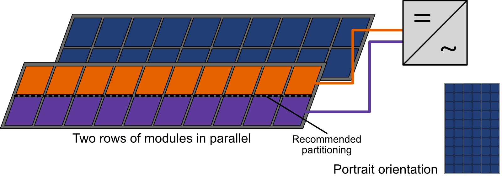 | 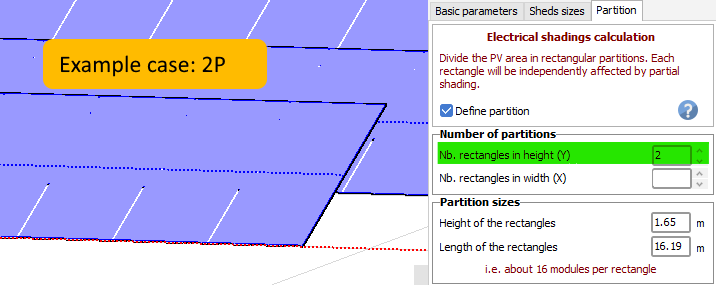 |
| xPU | module layout recommended | 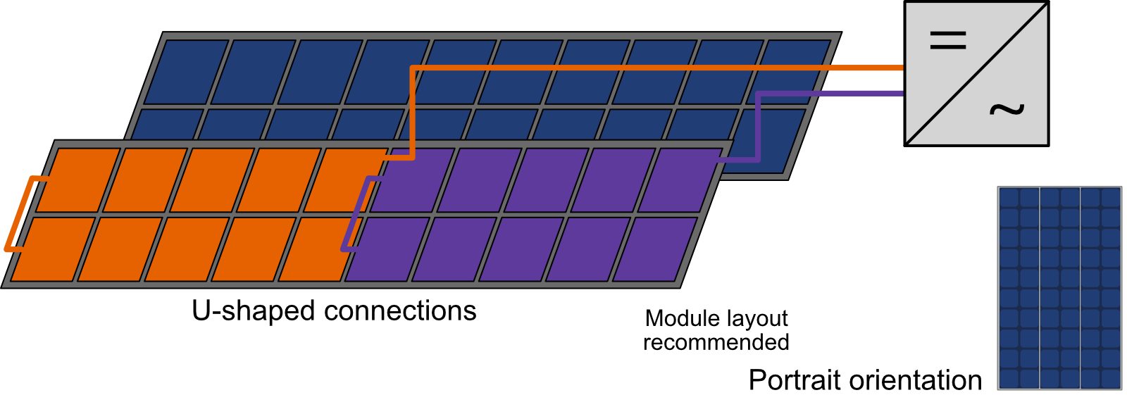 | |
| xT | 2x | 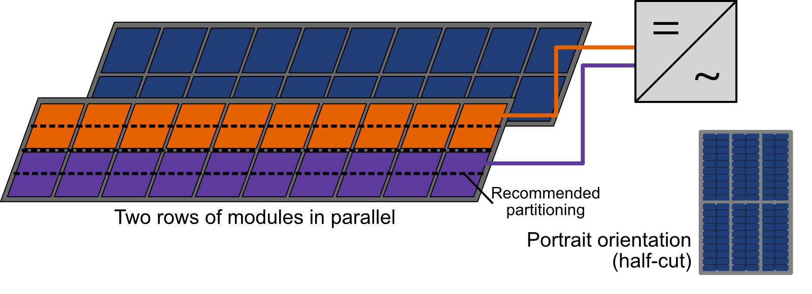 | 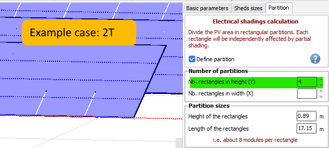 |
| xTU | x | 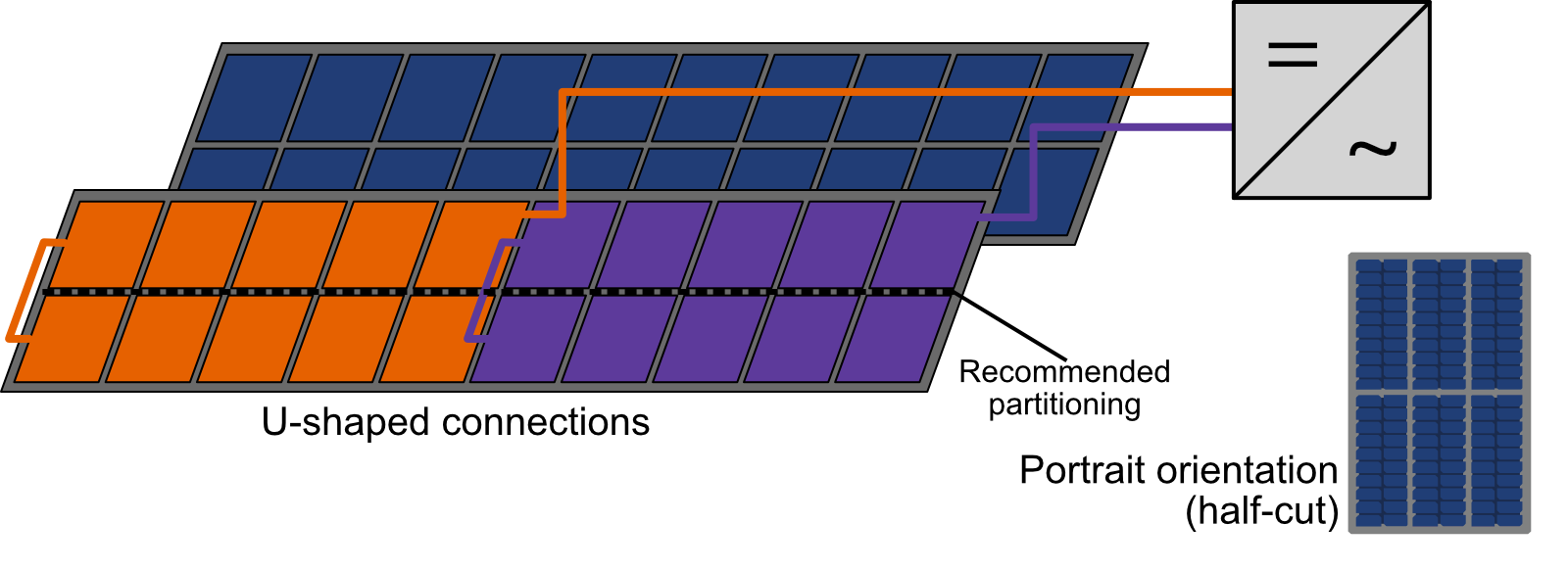 | 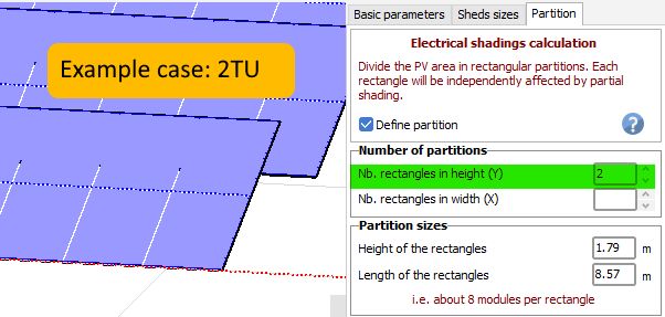 |
Result comparison
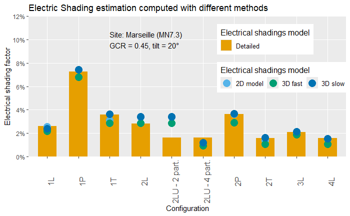
The agreement between the electrical shading values computed with the module layout and with the different approximation methods has been studied for PVsyst 8.0. Results for the most common geometries are shown in the figure below.
*Note that for the xLU case (2LU in the example), the choice of partitions yielding the most accurate approximation will depend on the climate (direct/diffuse ratio). Choosing x partition is preferred as it leads to an overestimation that can be corrected by a shading fraction. Using more than x partitions often leads to underestimations that cannot be corrected.
Extension of the partitioning to other tables
To proceed with the electrical calculation based on the partitioning in the simulation, the partition has to be defined for each table of the scene.
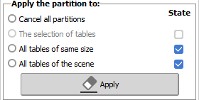
You can extend the definition of this table to the other tables of the scene.
| Cancel all partitions | allows to delete the definitions; the electrical calculation is not possible anymore until new definitions have been made. |
| The selection of tables | if you have defined a multiple selection in the global 3D scene, you can apply this partition to all selected tables. |
| All tables of same size | the partition may be specific for a set of identical tables. |
| All tables of the scene | defines all tables as "Partition defined" (even little tables 1 x 1), extends this choice when possible. |
Note that the number of partitions can also be modified for several objects at once from the list and management of objects (or CTRL+G in the 3D scene).
Model history
Up to 7.4.8
The partition recommendation for the xLU case was 3x partitions. Due to model updates and improvements, the recommendation was changed to x partition for PVsyst version 8.0