Mechanical definition
The aim of this page (tool) is to dispatch the PV modules (as defined in the sub-arrays of the "system" part) on the Tables defined in the 3D shading's editor.
Therefore the "System" and the 3D scene should be well defined before entering the "Module Layout" part.
The number of PV modules should correspond to the number of modules defined in the Sub-arrays for each orientation. Therefore you have a specific view (of the 3D tables) for each orientation.
Definitions of tables in the 3D scene
When defining your fields in the 3D scene, you are advised to use the option "By modules", so that the table's sizes are correctly predefined.
However freely defining tables with sufficient room for your modules is also possible. The tables will be resized at the output of this tool.
When opening "Module Layout"
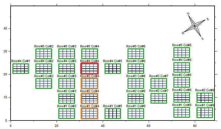
All the tables of your system (in one specific orientation) are presented as in the 3D scene. They are labeled as Rows and Columns, so that they may be easily identified. This numeration is automatic according to the geometrical arrangement, you cannot modify it.
The orientation is identified by a Compass on the top right of the drawing. If there are several orientations in your system, you can choose each of them by a combo-box.
On this example: the compass shows an orientation of azimuth 30° (south):
You select a table by clicking it (red contour).
You can define a multi-selection by Ctrl+Left Button, and deselct by Ctrl+Right Button (orange contour).
You have tools (icons on the right) for:
- Zooming IN / OUT (also with the wheel).
- Saving the tables picture as a *.BMP file.
- Choosing the label kind mentioned above each table (name of the table in the 3D scene, "Orient#, Row#, Col#", or more condensed, etc).
- Exchanging the string attribution (see next page).
- Desecting all your multiple-selected tables.
Operating panel
The blue panel on the top right always informs you about the state of your definitions, and the actions to be taken.
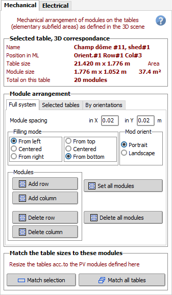
The "Mechanical" dialog:
- Shows the main characteristics of the selected table.
- Allows to dispatch the modules on the tables. This may be done for the full system, for the actual orientation if several ones, or for a selection of tables only.
- You can specify here the spacing between modules, the filling mode (when the table is bigger than necessary), the module orientation (portrait or landscape).
- If the 3D area is not sufficient some modules required by the "System" sub-arrays definitions may be missing. You can add a row or a line of modules if necessary (NB: if the table belongs to an array, all the tables of the array will be concerned in the same way).
NB: If necessary it is possible to suppress some modules in the table (by right-clicking on the concerned module). This allows to exactly adjust the number of modules required by the "system". This may also avoid using Polygonal fields without necessity. The use of polygonal fields is very special, it should be reserved to very specific BIPV cases.
However don't suppress too much modules as the shading calculation may be slightly affected.
Match the tables to modules
Finally, for the next steps the 3D tables should perfectly match the PV modules. If this is not the case you have to press the buttons Match this Table or Match all tables.
This is especially useful when you define a polygonal field in the 3D scene: the rough polygon (like for example a roof available area) will be initially filled with modules, you can add or suppress modules with the mouse, and finally you have to press "Match to Table" for adjusting the definitive polygon around the PV modules.
Completing all these requirements gives access to the "Electrical" tool.

