Detailed electrical losses: Module Layout
The detailed electrical loss calculation requires a precise localization of each PV module of the system, and its attribution to a given string/inverter input. These definitions are performed in the Module Layout part.
Calculation steps (model description)
This calculation replaces the usual shading factor calculation (which leads to shade polygons elaboration).
The electrical shading calculation has now to be performed for each sub-array corresponding to each MPP input of the inverters.
-
The shading (mask) calculation is applied to each corner of each sub-module (about 16-22 cells): a corner is or is not shaded.
-
For one sub-module:
- the irradiance (linear) shading factor is assumed to be proportional to the number of shaded corners (1/4 for one corner, 1/2 for 2, 3/4 for 3 shaded corners). This is therefore an approximation, acceptable as only applied to sub-modules on the border of the shade.
- the I/V characteristics of the partially shaded sub-module is evaluated (10% cells shaded for 1 corner shaded, 1/3 for 2, 2/3 for 3, 100% for 4 corners). It is again an approximation, but when inserted in the I/V full array characteristics the electrical effect is about the same as soon as the sub-module is shaded.
-
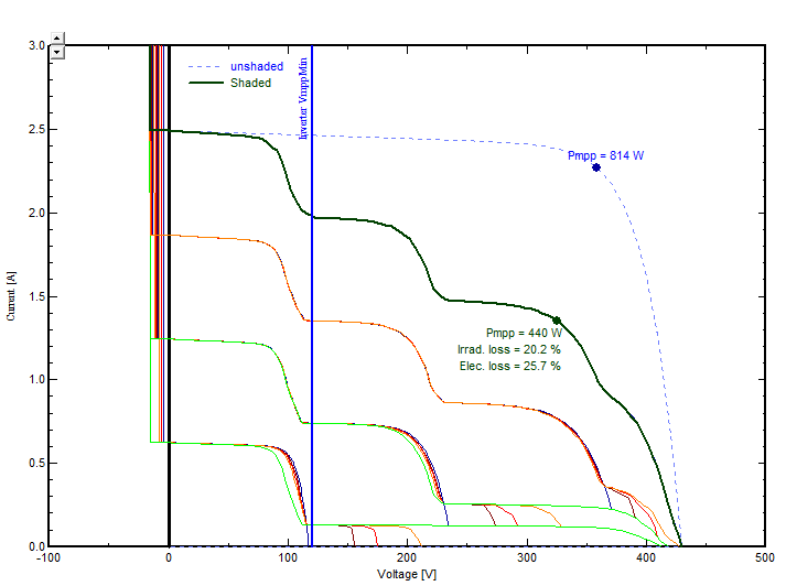
The I/V characteristics of all sub-modules of the string (shaded and not shaded) are added in voltage (series connection). This results in the I/V characteristics of this string. This calculation is done for each string.
-
The I/V characteristics of all strings are added in current (parallel connection). This gives the complete I/V curve at the considered MPPT input.
-
The inverter will now search for the maximum power point on this curve. This will fix the operating voltage (vertical line) and the operating current of each string. We can observe on the example below that the strings #1 and #2 will operate at their residual current corresponding to the diffuse part. Their production due to beam is completely lost.
You can have completely different figures where the MPP point is below the inverter's minimum voltage. In this case the voltage will clip on this value, and the shading loss may be very high. -
The shading losses are evaluated for this MPPT input, with respect to the unshaded Pmpp value. This loss is the sum of:
- the irradiance deficit ("linear" part), which is estimated using the number of sub-module shaded summits.
- the electrical mismatch losses which is the difference Pmpp (unshaded) - Ploss(irradiance) - Pmpp(shaded).
Irradiance and Electrical shading losses will appear separately on the loss diagram at the end of the simulation.
The following curve is available in the "Module layout" part, page "I/V curve".
