Orientations: system and 3D scene definition
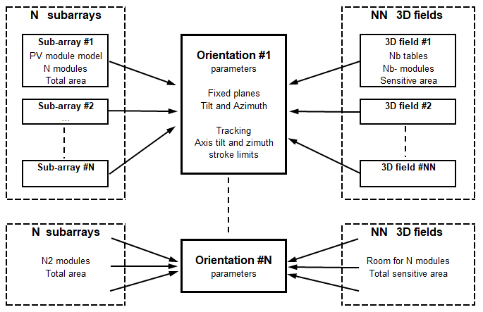
With PVsyst 8, orientations are now central to the system design, as illustrated in the graph below:
System (sub-arrays) definition
Sub-arrays are defined in the System menu. A sub-array is a group of identical strings, connected in parallel to an unique inverter model. Each string is defined by a single PV module model, possibly a single optimizer model, and a number of modules in series (NModSeries). A more detailed description is available here.
Usually a sub-array can only be attributed one orientation, even if for some specific systems up to 2 orientations can be attached to a single sub-array (Mixed orientations).
An orientation can be connected to several sub-arrays.
In a sub-array, the number of PV modules is \(N_{modules} = N_{Strings}*N_{ModSeries}\)
Orientations in the 3D scene
In the 3D scene, you can create 3D-fields. One field may be made of a single table, a tracker, or an array of tables / trackers. Upon creation, a 3D-field is automatically attributed an orientation. If no matching orientation is found (you are designing trackers but the only orientation is a fixed tilt) a new orientation will be created. Some exceptions are possible when using average orientations option.
When defining a 3D-field, you have to define as many modules as defined in the system, making sure the number of modules per orientation matches. As a consequence, you should have at least one 3D field for each orientation. This attribution can be done in 3D-field design by selecting either the right amount of modules, or the right sensitive area.
When quitting the 3D scene, PVsyst will check the consistency between your 3D definitions, the "Orientation" definitions and the electrical sub-arrays specifications. Small discrepancies are tolerated, but important differences will prevent the simulation to be run.
Tools for matching the Sub-arrays and 3D files
When elaborating a project, it is not always easy to match the 3D area with the number of modules defined in the sub-arrays. When defining the 3D fields, you have the possibility of defining tables matching exactly the sizes of your modules (fields sizes definition "by modules"). You are advised to use this option a often as possible.
Now when editing a 3D field, page "Basic parameters", you have the opportunity of opening the orientations list. And here you can find a balance of your present definition of modules / area:
Another way of getting a general view is to use the "System overview" tool. This will list all orientations, with all sub-arrays and 3D fields definition, as well as warning or error messages when useful.

