Orientation management procedure
This menu defines all parameters for the definition of an orientation.
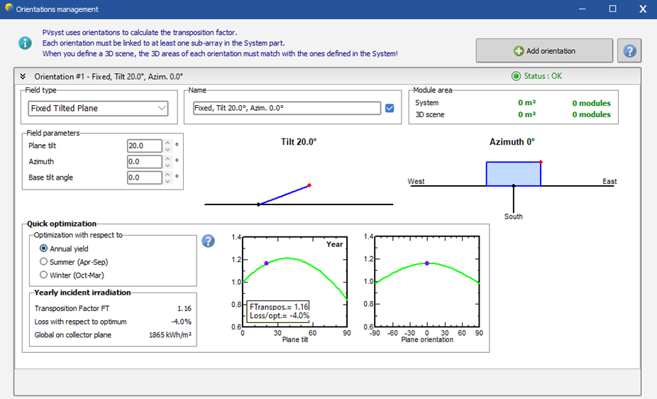
By default this menu will always start with a single fixed tilt orientation. It may be changed by selecting a different field type from the dropdown list on the top-right:
The right side shows the orientation's name. If the box on the right is checked, an automatic name will be defined according to the main parameters of the orientation. It can later be changed as desired. Having an unique and descriptive name is not required, but is recommended to ease the orientation identification in other menus.
Creating a new orientation
If not all arrays of your system have the same orientation or field type, you can click on Add Orientation at the top of the menu as many times as necessary.
It is possible to delete existing orientations, as long as there is at least one remaining.
Fixed plane systems
Fixed tilt plane
This is the simplest kind of orientation, only defined by the plane tilt and azimuth. The menu shows dynamic diagrams representing the field. The tilt is visible on the left side, while the plane azimuth is on the right, with the W/E axis representing the base of the table. You can modify the tilt and the azimuth directly from the view by dragging the red dots.
If tables (rectangular fields) are defined in the 3D scene, the base of these tables may be inclined compared to horizontal plane. This inclination, the Base tilt angle, is named base slope in the 3D scene. In this case the real plane orientation will be different from the orientation defined in the Fields Parameters
With fixed planes definition, PVsyst provides a quick orientation optimization tool indicating the energy yield as a function of the tilt and azimuth. This is a rough estimation, meant for judging how your orientation choice (violet point) will affect the yield compared to the optimum.
Domes
More and more industrial PV installations are now mounted in domes. This corresponds to a system with two sheds facing opposite directions.
When selected, PVsyst automatically creates a second orientation with opposite Azimuth and base slope. Domes are usually oriented East/West. However this is not a necessity, and the yield is almost independent of the orientation. The spacing between 2 rows of domes is usually very small, leading to a complete occupation of the available horizontal area. Therefore such a configuration is not suited for bi-facial systems, since no significant irradiance is reaching the ground below the sheds.
Seasonal tilt adjustment
Sometimes people want to optimize the PV production, by modifying the sheds tilt along the seasons. This option allows to modify the tilt 2 time per year. You have to specify the months for the winter and the summer position.
Unlimited sheds
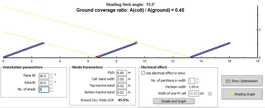
In addition to the orientation, this mode specifies the PV system (rows of PV modules). The idea behind is to have a full system, with mutual shadings, without requiring a 3D scene.
When selected, in addition to the orientation parameters, you will have to specify the sheds parameters:
- Number of sheds
- Pitch (distance between rows).
- Sensitive width
- Top and bottom inactive bands
The menu then shows the GCR as well as the limit angle (profile angle for which you begin to have mutual shadings).
It is also possible to specify the use of electrical shading effects (advanced option) during the simulation. In that case, you will have define parameters specifics to how your modules are distributed on the sheds.
Unlimited sun-shields
It is possible to define unlimited sun-shields on a façade, in similar way as with the unlimited sheds. This option is very rarely used, and is not advised, as the sun-shields are subject to high shading losses even in "normal" diurnal operation.
Tracking plane systems
Unlimited trackers, horizontal axis
Similarly to unlimited sheds, unlimited trackers can be selected for simplified or parametric studies of PV trackers system, without using the 3D scene construction.
In addition to the unlimited sheds parameters, you will have to define the Phi limits (mechanical stroke), the backtracking strategy, and the tracking calculation mode (astronomic calculation or irradiance optimization) to be used during the simulation.
The electrical shading parameters are only visible when the backtracking is not activated, as PVsyst current backtracking mode does not generates mutual shadings.
The menu also gives the opportunity of visualizing the tracker's behaviour according to the sun position. Simply click on the "Sun" and drag it in the window. If enabled, the animation will also display the backtracking strategy used during the simulation to.
Tracking, tilted and horizontal axis
Both options represent tracking systems where the rotating axis near horizontal in a North-South direction. The Horizontal axis is a particular case of tilted axis with a tilt = 0. This is the most common application of tracker systems. However on hills, the axis often follows the terrain slope, so that we cannot use the "Horizontal axis".
With these systems you will have to define the following parameters:
- Axis orientation (Will automatically change the tracker type if the tilt is changed to or from 0).
- Tracking limit angles.
- Phi limits (mechanical stroke)
- Central gap
Additional strategy parameters can be selected:
- Backtracking strategy
- Tracking calculation mode (astronomic calculation or irradiance optimization) to be used during the simulation.
- Wind stow defines a security rest position, to be set during the simulation when the wind speed is too high.
When defining an array of trackers, the construction in the 3D scene is mandatory, as this is the only way of calculating the mutual shading losses.
Tracking, vertical axis
This is a special case for high latitudes or special uses like floating tracking systems following the azimuth.
More details here
Tracking sun-shields
See the comments about sun shields; the competition between sun protection and PV production is not easy to optimize. The backtracking strategy is probably the only reasonable way to operate with sun-shields trackers.
Tracking, horizontal axis East/West
This configuration is not suited for PV systems. The tracking gain will be very low, and will not compensate the cost. You can define the parameters and use it in the simulation, but it is not advised.
Tracking two axis
The tracker will follow the sun, so that it is perpendicular to the sun's rays at any time. You have to define the stroke limits, keeping in mind that in summer, the sun may be at a very high azimuth in the morning and the evening, especially at high latitudes.
For arrays of 2-axis trackers, the backtracking strategy is much more complex. Mutual shadings can happen through the day on every side to the trackers. These shadings depend on numerous geometrical factors geometrical, such as the size and aspect ratio of the trackers as well as the distances between neighbouring trackers. In addition, once the set of position avoiding mutual shadings is found, the algorithm still has to find the optimal incident angle. For these reasons, the backtracking strategy is not yet implemented in PVsyst for two axis trackers.
Tracking 2-axis, frame North/South
This is a special configuration where trackers within the frame rotate around one axis and the whole frame around another axis. Thus, it has the same tracking properties as the Tracking two axis system with the plane always perpendicular to the sun's rays.
The main difference is on the the mutual shadings, because the tracker orientation within this plane will be different.
You have to define here the parameters related to the orientation. The mechanical frame characteristics (size, width, etc) will be defined when creating the 3D field representation. The backtracking may be done between trackers within the frame, not between adjacent frames.
Tracking 2-axis, frame East/West
This type of tracker is similar to the Tracking 2-axis, frame North/South but with the frame axis and trackers within the frame axis being inverted.
Again, the backtracking is applied to the internal trackers, i.e. east-west with tilted axis.


