Tool for Mixed orientation I/V curves analysis
In "Tools", click on the Electrical behaviour of PV arrays to open a tool dedicated to the composition of different I/V curves on a MPPT input.
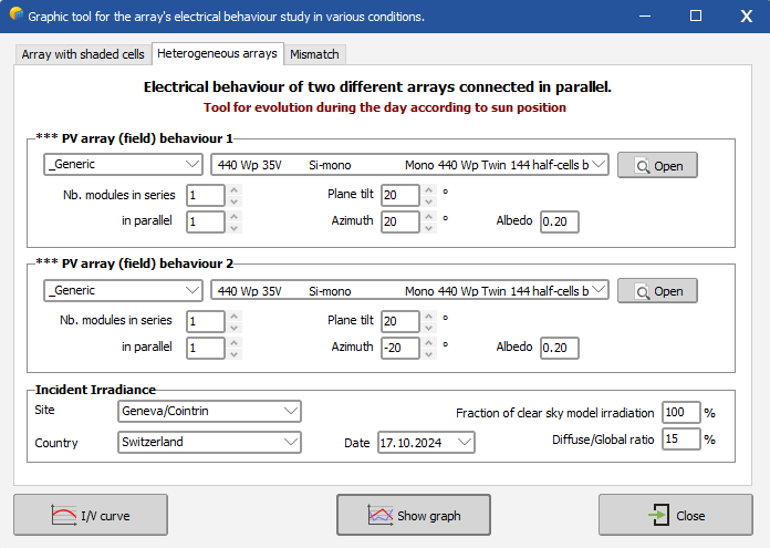
The heterogeneous arrays tab shows the characteristic of two sub-arrays connected in parallel. They can be set to have different orientations, collector's kind or number.
When connecting together the outputs of 2 different sets of strings, the resultant characteristic will depend on incident irradiances on each of the sub-arrays. It is therefore necessary to use an irradiance model capable to evaluate simultaneous irradiances under realistic conditions along the day. The tool uses a clear day profile, but with the possibility of modulating the global amplitude and the rate of diffuse irradiation. The temperature of the modules is calculated according to the respective irradiances. The user may use the scroll bar to modify the time-of day in order to evaluate the dynamic behaviour during the day when the orientations are different.
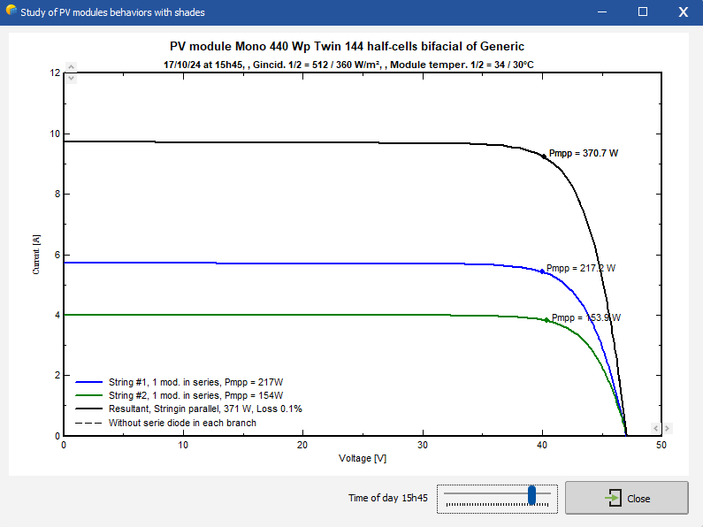
Example: Two identical arrays in parallel, with different azimuths: 
The graph shows the respective I/V characteristics of each sub-field and their resultant (current sum) when connected in parallel. The comment gives the nominal MPP value of each array, as well as their common value and the relative loss when connected in parallel. You can observe that when the array voltages are comparable the power loss is usually low, even for very different currents (different orientations along the day, or different parallel strings). In this case, the performances of each array are simply added together.
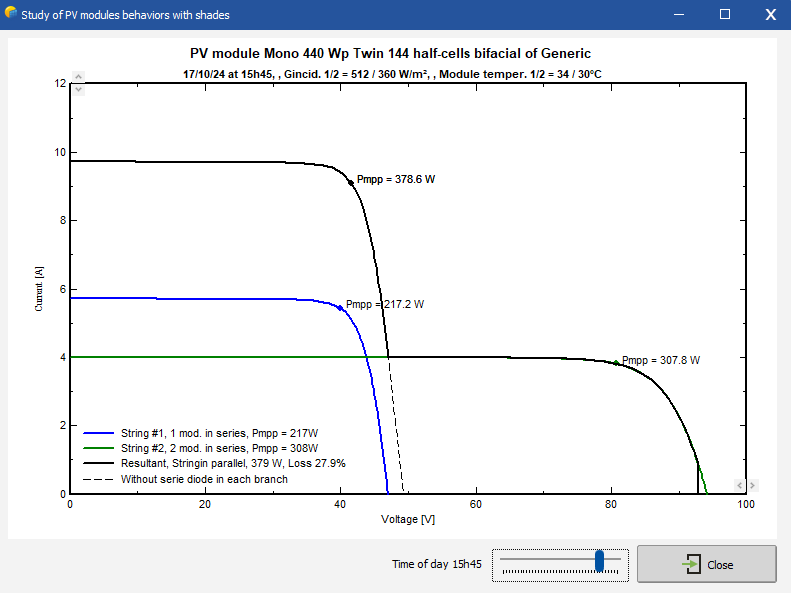
But for different voltages (different number of modules in series), the resultant characteristic shows two distinct maxima with an important power loss. This could also induce the MPP tracking device into error, as it may "choose" the secondary maximum.
Example: Two arrays in parallel, one with a single module and the other with two modules: 
If the arrays are expected to operate under different voltages (heterogeneous arrays or partial shading effects), it is important to connect blocking diodes in each string. The dotted line in the previous graph shows the resulting behaviour if these diodes are omitted: the production of the higher array may flow into the lower one, inducing a feeding power into the "overvoltage" region.
