String inverters, current limiting
Nowadays more and more inverters are proposed with many MPPT inputs (usually 8 to 12 or even more). These devices, named « string inverters », have usually MPPT inputs suited for one only string (or eventually 2), i.e. a current limit of the order of 10-15A. But:
- modern big module have sometimes an Isc current greater than this limit
- in many cases some of these inputs are connected to 2 strings in parallel.
"Use Multi-MPPT feature" option
As explained in the previous topics Power sharing , PVsyst provides 2 ways of simulating these devices :
- Either by checking the option «Use Multi-MPPT feature». In this case each input is considered as an independent inverter, with a power limitation = Pnom(inverter) / NbMPPT. This will lead to high overload losses.
- Or you uncheck this option. In this mode the input current remains limited as specified for each input, but the nominal power can be shared with all other inputs of this inverter. I.e. only the total nominal power of the inverter is limited, whatever the power of each input. This is the mode effectively applied by all inverters in the reality.
With string inverters, the right way is to uncheck the «Use Multi-MPPT feature» option.
Current limiting
The current limit for each MPPT input may be specified on the first page of the Inverter's definitions ("Input side" group).
Now with such a configurations, many people are astonished that the current loss is null in the simulation results, although the total « Nominal » current (Isc or Imp for each MPPT input) is far above the input current limit for some strings.
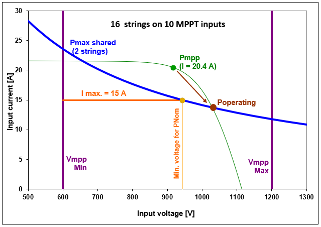
This is normal. Please have a look on the topic «Inverter Operating Limits ». For the concerned inputs, the Power limit (determined from the whole inverter capabilities) will displace the operating point towards higher values. Therefore the inverter Power overload limitation may occur before the input limit is attained. In other words, the loss will be accounted as Power overload instead of Current limiting loss. You will attain the current losses (horizontal line on the graph) when you have a low voltage (few modules in series) , or a high PNom (few inputs with double strings).
Let's show this by an example.
We suppose an inverter of PNom = 120 kWac, with 10 MPPT inputs, and a current limitation of 15 A per input.
We connect strings of 30 modules of 340 Wp, with an Imp = 10.2 A. This corresponds to a power of 9.4 kW per string under 1000 W/m2 and 45°C.
If we connect 16 strings, i.e. 4 inputs with 1 string, and 6 inputs with 2 strings: the available PNom for doubled strings inputs will be PAvail = PNom(Inv) - 4 * POper(1 string) = 120 kW - 4 * 9.4 kW = 82.4 kW on 6 inputs, i.e. 13.7 kW per MPPT input.
We have obviously a possible excess of current. However the overload conditions will move on the (PMax shared) curve, and the overload will be accounted as Power overload.
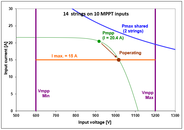
Now if we only connect 14 strings to this inverter, i.e. 6 inputs with 1 string and 4 inputs with 2 strings, the available power for the 4 double strings is higher:
PAvail = PNom(Inv) - 6 * Poper(1 string) = 120 kW - 6 * 9.4 kW = 63.6 kW for 4 inputs, i.e. 15.9 kW per MPPT input.
Therefore the power limit is not attained and the current limit will be activated for these 6 double inputs:
Therefore we see that the overload behavior conditions are rather complex. The PVsyst simulation treats correctly this situation.

