Bifacial systems results
The simulation results for a bifacial system can be examined in the Loss Diagram. In the upper section, the additional energy flux from the rear-side contribution appears to the right of the energy fluxes associated with the system's front side.
The following results are from the Demo Utility Project variant VC2: Bifacial Unlimited Sheds, which you can find in your workspace through the Project > Load Project menu.
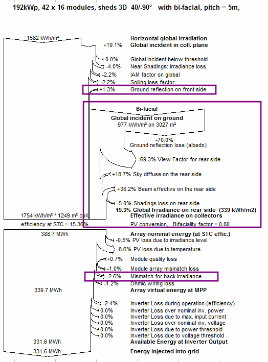
The first addition for the bifacial side is the Global incident on ground. Note that whilst this is an irradiance contribution on a horizontal plane, it is necessarily lower than the Global horizontal irradiation because the tables themselves cast shadows on the ground. The parameter Transparent fraction, defined in the "Bifacial system" window will also impact the Global incident on ground.
The irradiance on ground is multiplied by the albedo factor of the ground. The albedo defines how much irradiance is reflected, thus a yearly albedo factor of 0.3 results in a Ground reflection loss of 70%.
The View Factor is the fraction of the reflected light that effectively reaches a PV module backside. It depends on the relative position of the ground to the tables.
All these aforementioned contributions are normalized relative to the ground surface; instead, those that come hereafter are normalized relative to the PV surface.
In addition to the ground-reflected irradiance, PVsyst also calculates irradiance that directly reaches the rear of the PV modules with beam and diffuse components. Finally, there is a Shading loss that has been defined to 5% in this variant, in the "Bifacial system" definition window (parameter Structure shading factor). Note that no additional shading objects from the 3D scene are considered for the shading loss on rear side. PVsyst considers only row-to-row mutual shadings and structural shading losses.
Additionally, you will notice an extra contribution to the front-side irradiance—the Ground reflection on front side. While this contribution technically exists in monofacial systems as well, it is not calculated, since determining it requires the specific geometric parameters that are only defined in a bifacial system. However, for systems with a low tilt angle, its impact remains very small.
The addition from the bifacial system in the first part of the loss diagram refers only to the irradiance. The PV modules used in this simulation have a Bifaciality factor of 0.8, meaning that the rear side has 80% efficiency compared to the front side.
After the conversion the loss diagram proceeds as for a monofacial system with all the relevant losses and parameters, except for the additional Mismatch for back irradiance on top of the 2.2% of mismatch loss of the front side. In this variant, a mismatch loss factor of 10% was defined in the Bifacial system definition, resulting in 0.7% additional losses in the total system production. Indeed, this factor is only applied to the backside contribution, and is further reduced by the bifaciality factor.
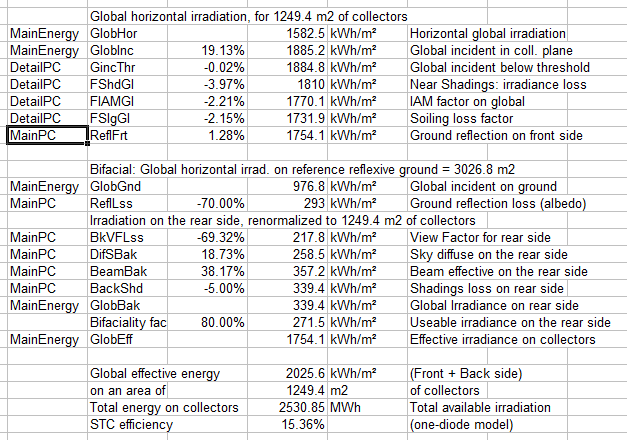
In the Report editor, you can also export the values into Excel (menu Export > Loss diagram values), which gives some explanations about how to calculate some values:
Detailed variables description:
| GlobGnd | Global incident on the ground This is the total irradiance reaching the ground area below the installation (beam and diffuse). This irradiance [W/m2] is referred to the reflecting reference area (in 2D models: proportional to the pitch). |
| ReflLss | Ground reflection loss (albedo) This is the loss of irradiance due to the reflection (1 - Albedo), referred to the ground reference area. |
| BkVFlss | View factor for rear side Each point of the ground is supposed to receive an irradiance (luminous power) specific to its position on the ground, and the sun's position. After reflection, this point will re-emit the same power in all directions (isotropic hypothesis, i.e., Lambertian distribution), according to the albedo factor. Now a part of this power will be intercepted by the rear side of the collectors, the rest is lost (sky). The view factor is the fraction of this interception for each given point. The total power received by the rear side is the sum of all ground points contributions. This power will result in an irradiance [W/m²], which is now normalised to the m² of collector area. Therefore when expressed as irradiance (not Power), this view factor should be multiplied by the Ground area and divided by the Collector area (i.e., 1/GCR). |
| DifSBak | Sky diffuse on the rear side This is the contribution of the diffuse irradiance, coming directly from the sky. |
| BeamBak | Beam effective on the rear side This is the contribution of the eventual beam coming directly from the sun: - with sheds, possible in the morning and evening when the sun passes behind the East or West. - with vertical East-West rows, when the sun is opposite to the front side, - with tracking systems, never. |
| BackShd | Shading loss on rear side Due to the mechanical structures (corresponding to the specified "Structure shading factor"). |
| GlobBak | Global irradiance on rear side Is the sum of all these contributions. This value is mentioned in [kWh/m²], and as a percentage of the GlobEff value. |
| EArrNom | Array Nominal energy at STC efficiency The reference energy of the array is defined as the sum of: - the GlobEff value, multiplied by the PV modules area and the STC efficiency, - the GlobBak value, multiplied by the PV modules area, the STC efficiency and the bifaciality factor. |
There are 2 other contributions linked to the bifacial model:
| MismBak | Mismatch for back irradiance This is the result of the Mismatch parameter specified by the user (see Bifacial Procedure). At this stage of the Array losses, on the results diagram this is referred as percntage of the full system energy. As an example, if you have specified a loss of 10% (of the bifacial contribution), and you have a bifacial contribution of 15% of GlobEff, this will be 10% of GlobBakEn / (GlobBakEn + GlobEff). NB: Here, the GlobBakEn is GlobBak * Bifaciality factor. |
| ReflFrt | Ground reflexion on front side This represent a contribution of the irradiance reflected by the close ground (between rows), and reaching the front side of the collectors (weighted by the IAM loss, very significant here). This contribution is indeed present in any PV system (bifacial or not). However nobody takes it into account, as its calculation involves the full bifacial model, with an accurate definition of the ground, its albedo and the geometry, and the full calculation of the ground points view factors. This contribution is very low with sheds and trackers systems, but becomes crucial with vertical East-West bifacial systems. |