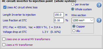
AC ohmic loss from inverter to injection point
Please refer to the basic Ohmic Losses definitions. Remember that the basic parameter defining the wiring losses is always the Resistance of the circuit.
Injection point
The injection point is the interface between your PV plant and the grid. It is where the energy E_Grid is effectively counted for determining the sold energy financial value.
Inverter output
The AC wiring losses may simply be defined by the distance between the inverter output and the injection point (or an eventual MV transformer), and the wire section.
The program will determine the minimum section of the wires, and only propose suitable sections if you want to increase it (2 undersized values are shown with a red background).
Inversely you can also specify a loss fraction (at your reference power, PNom or STC), and according to the chosen wire section, the corresponding wire length will appear, as well as the voltage drop for the reference power.
If several sub-arrays are defined, this AC loss may either be defined separately for each inverter (realistic wires), or globally for the whole system (virtual sum of wire sections).
After MV transformer(s): Medium Voltage line
In the same way, if you define one or several external transformer(s) you can define the properties of the MV line up to the injection point (or an eventual HV Transformer). This requires of course to also define the MV line voltage.
If there are several MV transformers, this will define the line at the output of each transformer. If the MV transformers are defined globally for the system, you should define an average length between all circuits.
NB: all the MV connexions to the common point (injection or HV transformer) are supposed to be independent (star connexion). In the present time you cannot specify MV transformers connected "in series" on a common bus. Such a mode would require complex calculations (and sizing requirements) wich will be implemented in a next version. As an example, if you want an equivalent loss between N equidistant transfos, the second section should have a wire section of 4 time the first one, the third section 9 times, etc (each is the square of the transfo order).
After HV transformer(s): High Voltage line
Finally for very big systems, you may define a HV transformer for feeding HV grid line (> 100 kV). Again, you have to define the grid High Voltage and the length of the line up to the injection point.
Securities with weak (remote) grids
Please note that the sizing of the cables up to the injection point may be very important when the grid is "weak" (remote grid in country regions). This is often a limitation on the possibility of Power injection (grid power limitation).
When injecting power into the grid, the grid voltage will increase due to line impedance. Your inverter is equipped with a safety device, which should cut the production when exceeding a given maximum voltage. Therefore you are advised to minimize the voltage drop within your installation, at least in the parts where you have the possibility of doing this. You cannot act on the grid voltage increase at the injection point: this is the responsibility of the grid manager.

