PV Module reverse characteristics for IBC modules
IBC cells
In some new cell technologies (IBC: interdigital back contact), the reverse voltage can become very low due to implementation of a pseudo-diode (tunnel effect) on the rear side of PV cells. The reverse characteristics may attain 2.5V under the operating current of the module.This is often mentioned as "the cell includes its own by-pass diode". This should have consequences on the electrical shading calculation.
Implementation in the Module Layout calculation
The "Module Layout" electrical shading loss calculation indeed accounts for I/V reverse characteristics. For the particular behavior of these modules, we should correctly define the reverse characteristics of the cell, which is determined by the factor Arev. The model is simply Irev = Isc + Arev * Vrev². This parameter is specified in the PV module dialog, page “Additional data => Secondary parameters”. 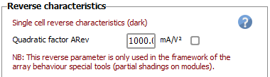
As an example, for getting a reverse value of 2.5 V for a current increase of 10 A, you should define ARev = 1100 mA/V². With such a value the shading calculation will use the sub-module I/V characteristics like this, that you will be able to see by opening the option “Tools => Electrical behaviour of PV arrays”, page “Array with shaded cells”, option “Cells and reverse characteristics”: 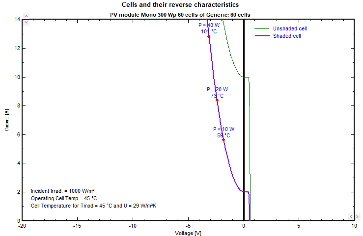
This characteristic will be used in all electrical shading simulations in the Module Layout tool.
Effect on the electrical shadings calculation
However, you cannot expect a dramatic gain from such behavior.
Intuitive explanation
For simplification, consider a module of 60 cells in series, i.e. a submodule of 20 cells (Vmp roughly 20 * 0.5V = 10V). If 1 cell is shaded, at the operating current of the string (say 10 A), it will lose 2.5 V of reverse voltage, that is, 2.5 V / 10 V If 2 cells are shaded, this will lose 2 × 2.5 V, that is, 5 V / 10 V If 3 cells are shaded, this will lose 3 × 2.5 V, that is, 7.5 V / 10 V, meaning only 5 cells remain active If 4 cells are shaded, the shaded cells' voltage reaches the maximum voltage of the submodule, you lose the entire production of this submodule. Beyond that, the voltage of the shaded cells will exceed 10 V + 0.7 V, the bypass diode will become active (i.e., bypass the current). NB: Shading of a single cell is a very special situation and quite rare. Shading 2 cells per submodule arises when you have shades on the bottom cells of modules in portrait.
Visualization
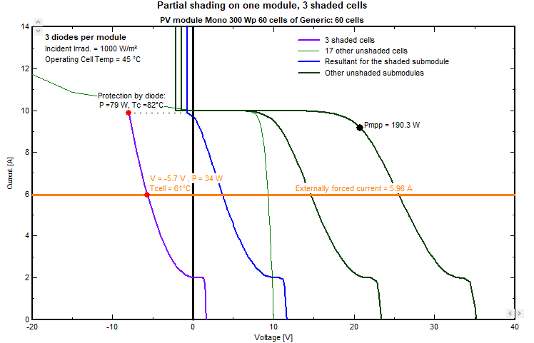
You can visualize this on the previously mentioned tool, option “One shaded module”. If you choose the module “Generic – PV module Mono 300 Wp – 60 cells” On the page “Cells and reverse characteristics", you define Arev, mean value” = 1100 V (i.e. Vrev = -2.5V under 10 A) You define 3 bypass diodes and 3 shaded cells, You will obtain the following plot, where you see that the shaded submodule’s contribution (blue curve) is quasi-null at Impp. You can try with 4 shaded cells; the bypass diode will activate, and the module will behave like any other standard module.