Pump - Model description
See also the General Requirements governing the elaboration of this model.
Variables
Let us define the following variables:
- Up, Ip = Voltage and current applied the pump.
- Pp = Up * Ip = Input power of the pump
- Uc, Ic, Pc = Voltage, Current and Power applied to the input of the power converter, if any.
- FR = Flowrate produced by the pump
- HT = Total Head, sum of the Static Head (related to the difference between input and output water levels), and Dynamic Head, due to friction losses in the pipes and system. Dynamic head is dependent on the flowrate, and will be computed by the system simulation process.
Model Structure
The pump characteristics may be considered as a set of operating points represented as a surface in the 4-variable space, i.e. corresponding to the equation:
Φ (Up, Ip, HT, FR) = 0.
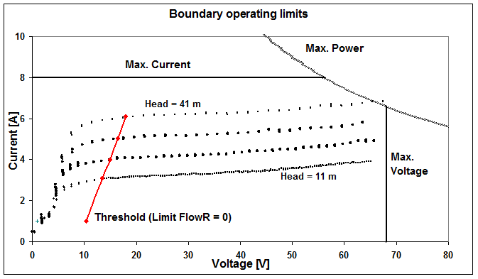
This function will be defined on an operating domain, which is bounded by some limits (usually specified by the manufacturer):
- Maximum voltage applied to the motor-pump,
- Maximum electrical power,
- Maximum current,
- Maximum Head (implies maximum current),
and toward the low values:
- Power threshold for starting operating (i.e. not null flowrate), which is a function of the Head.
 |
| Boundary limits of the operating domain and I/V measurements for pump Watermax BU (CIEMAT measurements1) |
The equation Φ=0 implies that only 3 of the 4 variables are independent. Therefore the model will provide relations allowing to calculate any one of the above variables, as functions of two others. The basic relations are:
- Ip = f (Up, HT), the fundamental relationship which will be used for determining the operating point when directly coupled to a PV array.
- FR = f (Pp, HT), completing the preceding relation for determining the corresponding flowrate.
- Pp = f (FR, HT) will be used for example for sizing the PV array power, or for determining the efficiency.
The other relations may be obtained by numerically inverting these 3 fundamental ones.
As a complement, the model also provides functions for determining the Power, Voltage or Current threshold (i.e. the boundary where the flowrate drops to zero) as function of the Head.
The Phenomenological Model
The problem is now to determine this function Φ. We would like to avoid references to technology-specific parameters, that is to physical models describing the motor or pump. Therefore our model is mainly based on the known performances, i.e. the operating points either specified by the manufacturer, or measured by other sources.
If these points are sufficiently well distributed over the operating domain, they will completely define the pump behaviour. The informatic model has to interpolate between the given points; in practice, it will perform cubic interpolations between points, and linearly extrapolate the data up to the boundaries. Therefore this model is just a phenomenological one, without any physical contents.
Physical assumptions will be necessary only if the data set is not sufficiently well distributed for allowing extrapolations within the entire operating domain. These very general assumptions will be established according to general behaviours observed when measuring a great number of pump technologies. These could probably be refined during our future works. Of course this lack of primary information in the basic data will result in lower accuracies of the model's predictions.
In practice the manufacturers use to specify the performances of their products by giving different kinds of data sets. We identified 5 of them, which may be input directly in the PVsyst model. Each one has to be treated specifically in the model; that is, the algorithms of the basic functions mentioned above will be different for each kind:
- Given Ip and FlowRateas f(Head) for fixed Voltage, usually for Positive Displacement Pumps.
- Given Power and FlowRateas f(Head) for fixed Voltage, equivalent set, as U is defined for each point.
- Given FlowRate as f(Power) for fixed Heads, usual for solar centrifugal pumps, but doesn't include Current/Voltage specification, therefore only suited for configurations with converter.
- Given Head and Poweras f(FR), fixed voltage or speed is the usual way of defining standard centrigugal pumps for grid operation. This definition leads to the "Similarity Laws" model.
- Given Head and Efficiencyas f(FR), fixed voltage or speed is equivalent to the preceding, the power being easily deduced for each operating point.
-
M. Alonso-Abella (CIEMAT)
Detailed measurements of several pumps, 2004.
Private communication, 2004. ↩