Base Slope
Base slope effect describes the phenomenon observed in solar panels that are installed on sloping terrain. This refers to how the inclination of the ground influences the positioning and performance of the panels.
This phenomenon impacts how solar panels' positioning and orientation are adjusted according to the land's incline, directly influencing their performance.
To grasp the concept of how terrain slope affects solar panel orientation, let's use a simple visualization technique. Imagine using a piece of cardboard to represent the solar panel plane, which we'll refer to as the PV plane.
- Initial Positioning: Begin by inclining the cardboard towards the south, as if you're facing south. This simulates the initial orientation of your solar panel towards the optimal solar exposure.
- Adjusting for Roof Slope: Next, tilt the base of your cardboard to mimic the slope of your roof or the terrain where the solar panel will be installed. This adjustment represents the real-world application of installing panels on a sloped surface.
- Visualizing the New Orientation:
- Imagine a horizontal line passing through the center of your tilted cardboard (the PV Plane). This line will appear oblique in relation to the edges of your rectangular cardboard.
- The new orientation (azimuth) of the PV Plane is perpendicular to this imaginary line. Surprisingly, even slight tilts can result in the azimuth deviating significantly from the south.
- To determine the new tilt, consider the slope of a line perpendicular to the horizontal line, within the tilted plane of the cardboard. This slope represents the panel's new tilt angle.
For precise calculations, especially when dealing with complex installations, it's necessary to define the normal vector to the PV Plane and apply rotation matrices to account for both the tilt and azimuth adjustments. This mathematical approach, while accurate, is not as straightforward as our visualization method.
PVsyst categorizes solar panels based on their orientation to manage the complex scenarios presented by uneven terrains. The software employs a 1° tolerance rule for the normal vector of PV tables, effectively grouping panels with similar orientations. This feature is particularly useful for projects involving complex 3D scenes with varying topographies.
On flat ground, the azimuth and inclination of the pivot tables remain constant and the terrain has no influence. However, panels placed on sloped terrain will adapt to the slope and inclination, resulting in new orientation values.
PVsyst includes a dedicated educational tool to aid users in comprehending the base slope effect. From the 3D scene menu, select "Tool" and then "Orientation Understanding Education Tool". This tool is designed to visually demonstrate how changes in panel inclination affect orientation.
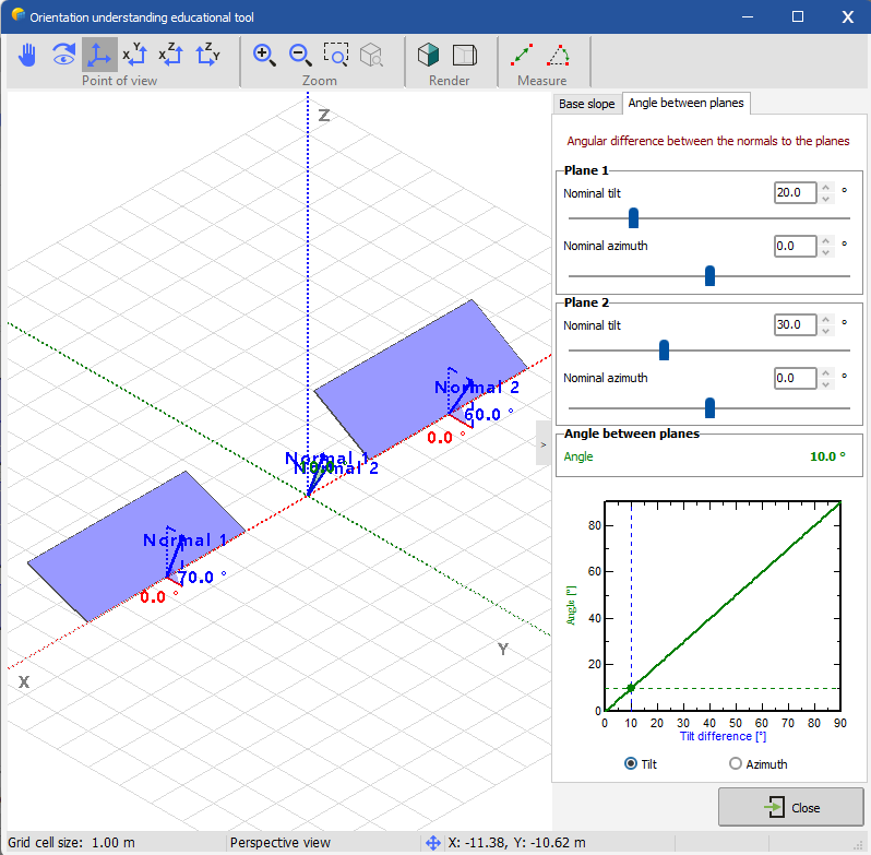
A side-by-side comparison of two panels is displayed, where initially, both panels share the same orientation and normals. Adjusting the inclination of one plane illustrates how its normal vector- and thus its orientation - changes relative to the other panel.
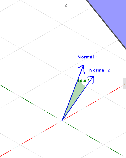
For instance, if the inclination of the first panel is changed to 20°, the difference between the normal vector reaches 10°.
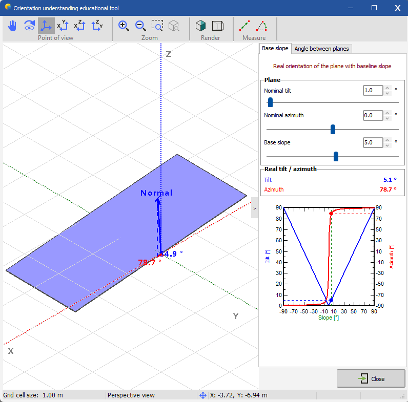
The result of the normal vector after applying the base slope is illustrated in the "Base Slope" tab.
If we start with a nominal inclination of 30°, an azimuth of 0° and adding 5° to the base inclination, the real inclination azimuth box shows values that are slightly different from the nominal plane.
For another example, if we set an inclination of 1° and apply a base slope of 5°, the real azimuth become 78.7°, whereas with an inclination of 20°, the real azimuth drops to 13.5°. This is because we measure the normal vector to the PV plane.
As for an imported scene, a nominal inclination of 20° and an azimuth of 0° is defined with a specific topography. PVsyst generates different orientations with a tolerance of 1° between each nominal vector. In practical applications, wiring each panel based on slight orientation differences identified by PVsyst is not feasible. To address this, PVsyst allows users to adjust the tolerance for normal vector identification, effectively reducing the number of unique orientations and simplifying project planning.
- Adjusting Tolerance: Increase the tolerance parameter in PVsyst’s orientation identification settings. This adjustment groups panels with minor orientation differences together, streamlining the installation process.
- Applying Changes: By setting a tolerance, for example, of 20 degrees and selecting Identify orientations, PVsyst consolidates panels under fewer orientations. This simplification is crucial for efficiently managing large-scale installations across uneven terrains.


