Basic data page (Li-Ion)
Battery identifiers
As for any PV component:
- Model and Manufacturer will appear in the batteries choice lists.
- Data source usually refers to the data source (most often Manufacturer, may be an independent institute or your own measurements).
- File name should have the extension '.BTR'
Technology and category
- Technology specifies the chemistry of the battery. Most of the PV systems use the Lithium Iron Phosphate (LiFePo4 or LFP), which is the better suited for steady systems (a little bit lower power density, but higher security).
-
Category: the battery definition in PVsyst (*.BTR file) can handle different levels of battery devices. You can choose:
- Single cells (cylindrical, pouch or prismatic cells),
- Modules (blocks): you will have to specify the number of cells in series and in parallel,
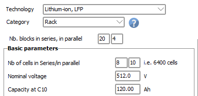
- Cabinets or racks: you will have to define the number of blocks in series and in parallel
- Container: this is not defined as a battery device. The number of cabinets/racks will be specified within the project.
Therefore the dialog allows to take a cell as basis, and construct a complete device to be used in the project. The cell contains the main basic parameters of the device. The extensive parameters will be multiplied by the number of cells in series and in parallel.
As an example, the following definition (with cylindrical cells of 3 Ah) will give a system of 512 V and 120 Ah: 
Other basic parameters
The other basic parameters are the main values to be specified from a datasheet. They may be defined either per cell, or for the whole device.
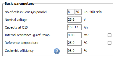
- Number of elements in series and parallel for the block; on the datasheets, they are sometimes noted 8S50P (for the example above), for the number of cells in series and in parallel,
- Nominal voltage: is depending on the chemistry; this is a "nominal" value, the exact voltage at 50% SOC is defined independently (next page). This determines the nominal voltage of the full battery device.
- Nominal capacity: the reference capacity is specified for a discharge rate in 10 hours (noted C10) and for a reference temperature of 20°C. Capacity behavior according to discharge rate and temperature will be defined in the next page.
- Internal resistance is a nominal value at reference temperature. If not specified you can ask for a reasonable default (i.e. a voltage drop of 16 mV par cell at C10, modifiable in the Advanced Parameters). The resistance is dependent on the temperature (see the next page), which is the source of the voltage temperature dependency.
- Reference temperature is the reference temperature used by the model to set 2 corrections: the internal resistance correction as a function of temperature, and the capacity correction as a function of temperature. It is sometimes specified on the datasheets (20°C or 25°C).
- Coulombic efficiency (or faradic or current efficiency), is the discharge/charge cumulative currents balance, in [Ah]. This is supposed to be 96% for li-ion batteries. In the model, this efficiency is applied to the charging current.
NB: Do not confuse the Coulombic efficiency with the battery global efficiency. The global efficiency in operation reported by some manufacturers is of the order of 90 to 95%. It includes all other losses; and namely the internal resistance, which induces an increase of the charging voltage and a decrease of the discharging voltage, therefore an additional contribution to the energy loss.
Tool for renormalization to C10
For li-Ion batteries, the nominal capacity is usually defined for a discharge rate of 2 hours (0.5C) or 5 hours (0.2C). This little tool allows to recalculate the PVsyst nominal value at C10 (0.1C), from this value and the capacity variability according to the discharge rate.
NB: this tool gives you the value to be defined as "Capacity at C10", but it doesn't replace the value: you have to do that explicitly.
Behavior at limits
For Li-Ion batteries, we have to define operating limits, almost always mentioned on the datasheets.
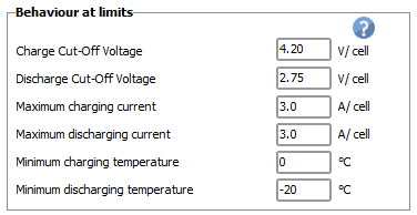
- Charge Cut-Off Voltage specifies the maximum allowed voltage when charging.
- Discharge Cut-Off Voltage specifies the minimum allowed voltage in discharge state. These values are never attained by the voltage model of PVsyst. They correspond to extreme conditions.
- Maximum charging current,
- Maximum discharging current, These values are mentioned on the datasheets, but it is not always clear whether they correspond to Maximal or Nominal operating values. The usual values of maximum current are usually close to the capacity (i.e. corresponding to a charge/discharge in one hour, C1). Nominal values are in most of cases half (i.e. discharge in 2 hours).
NB: Another general limit of charging/discharging rate is specified in the advanced parameters, fixed at C2 for Li-Ion. During the design of a system, exceeding one of these values will lead to an error message.
- Minimum charging temperature,
- Minimum discharging temperature, are always mentioned on the datasheets. Temperaturs below these limits may damage the battery; but these limits are not used in the simulation.


