|
<< Click to Display Table of Contents >> Validations on old versions of PVsyst |
  
|
|
<< Click to Display Table of Contents >> Validations on old versions of PVsyst |
  
|
The seven tested grid-connected installations
We have carried out detailed validations of the programme, using the data from 7 grid-connected systems, whose detailed characteristics appear on table 1. These systems have been chosen, on the one hand for the quality of gathering data, and on the other hand as an attempt to represent a variety of different situations: sizes of 0.5 to 100 kWc, fields in sheds or integration (roofing, facade), types of collectors (Si-mono, Si-poly, or amorphous), types of climates (plain, mountain, etc.), possible near shadings.
The validations have to be carried out carefully using measured data, with an hourly or sub-hourly time step, over sufficient periods (one year). According to the measurement's parameters available, we have tested the various stages of the simulation, giving special attention to those which involve the most delicate physical models.
Installation |
N 13 |
Marzili |
LESO-Sheds |
SIG |
EIV |
LESO-LRE |
LESO-USSC |
Site (Switzerland) |
Domat-Ems |
Berne |
Lausanne |
Genève |
Sion |
Lausanne |
Lausanne |
Field: type Tilt angle Azimuth |
Anti-noise-wall 45 ° 25 ° East |
Sheds 35 ° 37 ° East |
Sheds 45 ° South |
Sheds 35 ° 9 ° East |
Sheds 45 ° South |
Facade 90° South |
Demosite 28° South |
Installed power Field area |
104 kWc 967 m2 |
25.6 kWc 170 m2 |
12 kWc 111.6 m2 |
7.6 kWc 61.5 m2 |
3.2 kWc 31.7 m2 |
3 kWc 28.6 m2 |
0.45 kWc 8.2 m2 |
Collectors: manuf. Type Nominal Power STC Measured Power STC Measurements Technology |
Kyocera LA361 J48 48 Wc 48 Wc Ispra SI-poly |
BP Solar BP495-Saturn 95 Wc 88 Wc Ispra SI-mono |
Solarex MSX 60 60 Wc 55.1 Wc TISO SI-poly |
Arco-Solar M55 53 Wc 50.8 Wc Ispra SI-mono |
Photowatt BPX 47500 48 Wc 40.3 Wc TISO SI-poly |
Flagsol Optisol/LESO 250 Wc
Manufacturer SI-poly |
USSC (USA)
17 Wc LESO a-Si:H tandem |
Irrad. transposition: MBE (transpos.-meas.) RMSE (daily val.) RMSE (hourly val.) |
2.8 % 5.5 % 11.7 % |
-0.9 % 3.2 % 7.8 % |
-6.0 % 9.6 % 15 % |
-2.2 % 2.9 % 5.1 % |
9.3 % 5.5 % 10.4 % |
|
-11.3 % 7.7 % 11.4 % |
Coll. Temperature model Wind velocity measurement K factor (input param.) MBE (simul-measure) RMSE (hourly val.) |
No 29 W/m2K -0.3 °C 2.1 °C |
No 29 W/m2K -0.5 °C 1.5 °C |
No 29 W/m2K -0.03 °C 2.7 °C |
Yes 20 + 6 vvent 0.8 °C 2.1 °C |
No 29 W/m2K -0.7 °C 3.8 °C |
No 13 W/m2K -0.2 °C 3.7 °C |
No 23 W/m2K 0.0°C 2.8 °C |
PV-Field DC energy Simul. Base: MBE (simul-meas.) RMSE (daily values) RMSE (hourly values) |
Plane irrad. 5.6 % 8.7 % 11.0 % |
Plane irrad. 1.0 % 10.0 % 15.5 % |
(field #3) Plane irrad. -0.7 % 2.2 % 5.2 % |
Horiz. irrad. 0.7 % 5.0 % 9.8 % |
Plane irrad. 3.1 % 3.4 % 6.5 % |
Horiz. Irrad. 1.4 % 10.8 % 17.7 % |
Plane irrad -13.6 % 8.9 % 13.4 % |
System AC output MBE (simul-meas.) RMSE (monthly values) RMSE (daily values) RMSE (hourly values) |
5.5 % 5.4 % 8.3 % 10.8 % |
1.0 % 4.5 % 9.9 % 15.3 % |
-0.7 % 1.1 % 2.4 % 5.5 % |
1.9 % 1.7 % 5.3 % 9.7 % |
2.8 % 1.2 % 3.3 % 6.5 % |
2.7 % 8.2 % 12.7 % 19.0 % |
-12.8 % 7.5 % 8.5 % 12.5 % |
Table 1. - Summary of the 7 tested installations:comparisons between simulation and measurements.
(A positive MBE indicates that the simulation overestimates the measured values)
Incident irradiation models
The first delicate stage is the treatment of the incident irradiation in the collector plane: it involves models for the estimation of the diffuse irradiation (from the global irradiation) and for transposition. These models have been otherwise studied [Perez et al], but proved to be the weakest link in the comparison process, with differences reaching more than ten percent for some of the data used.
For the SIG installation at Geneva, the only site where measurements of the horizontal diffuse irradiation is available, the deviation does not exceed 2 to 3%.
But other sites show differences going up to more than 10%. It should be emphasised that these results are highly dependent on the quality of the instruments used for the irradiance measurements (especially the calibration and sometimes the positioning). We supposed that the standard deviation in hourly values is a good indication of the performances of the model itself, and in this respect, the installation of Marzili (MBE=1% and hourly RMSE < 7.8%) confirms their validity. The mediocre results of the LESO can be explained by the considerable distance (several hundred meters) between the horizontal solarimeter and the measurement in the collector plane.
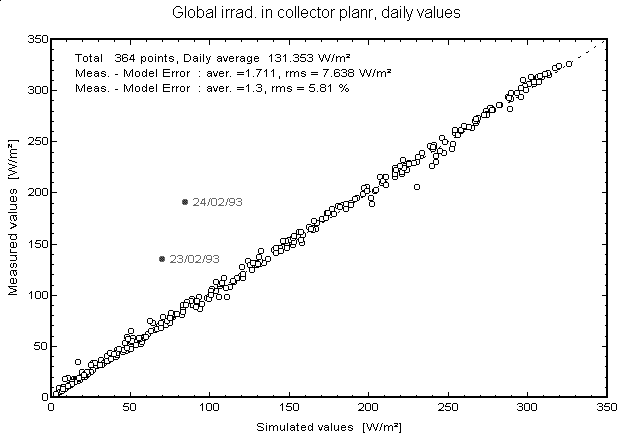
Fig 1a. - Measurement-Simulation Comparison for Incident Irradiation,
Marzili installation, daily values
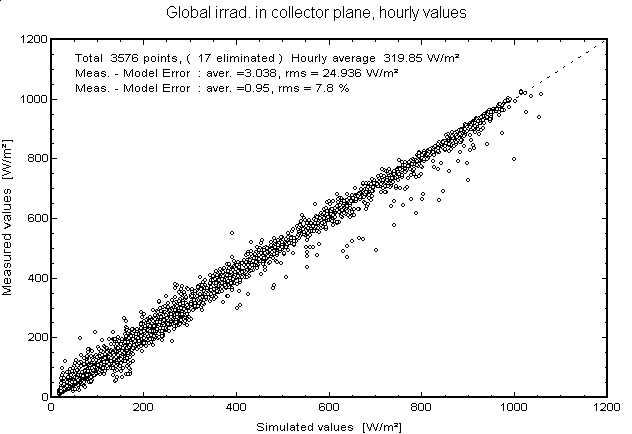
Fig 1b. - Measurement-Simulation Comparison for Incident Irradiation,
Marzili installation, hourly values
Array temperature model
The second model is the estimation of the temperature of the PV field using values of ambient temperature and irradiation. This temperature only acts as an auxiliary parameter in the calculation of the electrical production of the field, and its specification is not critical. Our model, resulting from a simple thermal balance, gives remarkable results. By using the default value suggested by the programme (k=29W/m²k) for all the collectors without back-covering, and by adapting this value for the integrated installations, we obtain, in all cases, errors lower than 1°C, with hourly dispersions of 2 to 4°C at the most.
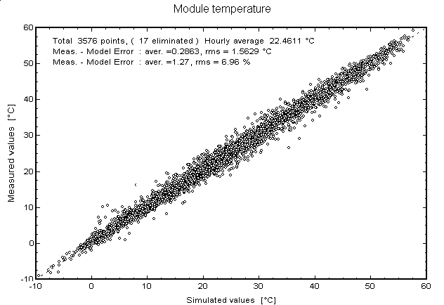
Fig 2. Comparison of the measured temperature with respect to the model
Marzili Installation.
Array output calculation
The electrical output, measured at the collector array terminals (DC energy), is calculated by the simulation on the basis of the incident irradiation (given the shading and non normal incidence corrections), the temperature of the modules, and the collector model (operating at MPP), keeping in mind the ohmic losses of the wiring and the module's mismatch. The excellent results obtained especially in LESO-sheds, the SIG or at the EIV, show that these models work perfectly, at least for silicium crystalline modules.
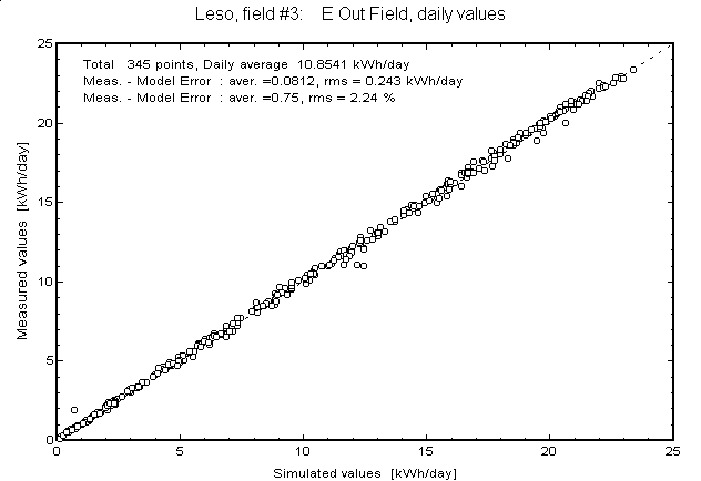
Fig. 3a. - Simulation-Measurement Comparison for the output of the PV field
(LESO-sheds installation, daily values)
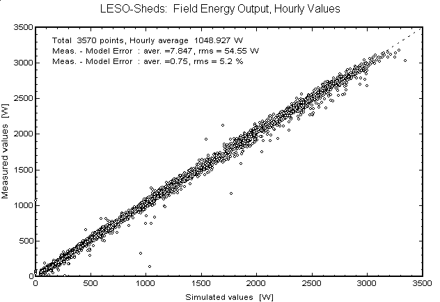
Fig. 3b. - Simulation-Measurement Comparison for the output of the PV field
(LESO-sheds installation, hourly values)
Amorphous tandem technology
The LESO-USSC installation, equipped with a:H-SI tandem amorphous collectors, has shown one of the limits of the collector's model used. Table 1 shows that the global results of the field are clearly underestimated by the simulation. Fig. 4 shows that the values with strong beam are very well reproduced (MBE=0.5 %), while the points of pure diffuse irradiation are clearly under-evaluated. This is attributed to the fact that this type of collector is more sensitive to diffuse irradiation, which cannot be reproduced by our model which does not take the spectral distribution of the incident irradiation into account.
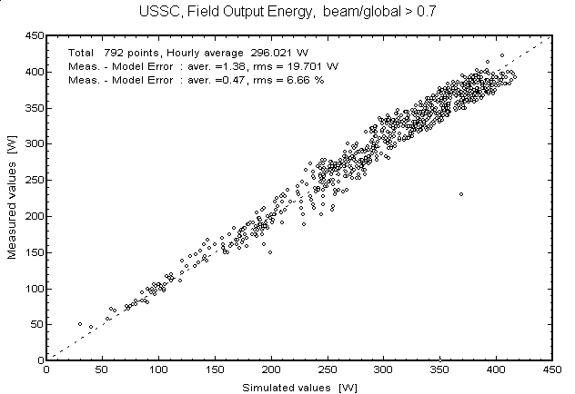
Fig 4a. - Comparisons for the amorphous collectors of the LESO-USSC, strong beam
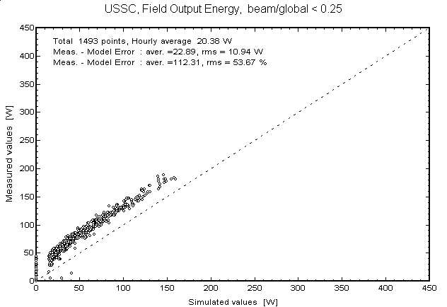
Fig 4a. - Comparisons for the amorphous collectors of the LESO-USSC, purely diffuse irradiation
Inverter modelling
Inverter's operation modelling does not give any special problems, except the exact determination of the power efficiency profile: the programme offers a specific tool to superpose the characteristic of an existing model (present in the component library) on the measured input/output data of the inverter. The exact profile corresponding to the data can then be adjusted interactively by the user, and it can be assumed that the residual errors of the simulation are not imputable to the calculation model of PVsyst, but only to the inaccuracy of the parametrisation of this inverter efficiency.
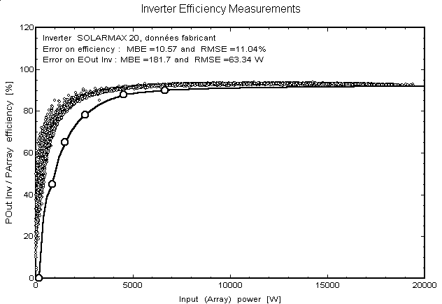
Fig 5a. - Inverter response, with standard available inverter specification (Marzili).
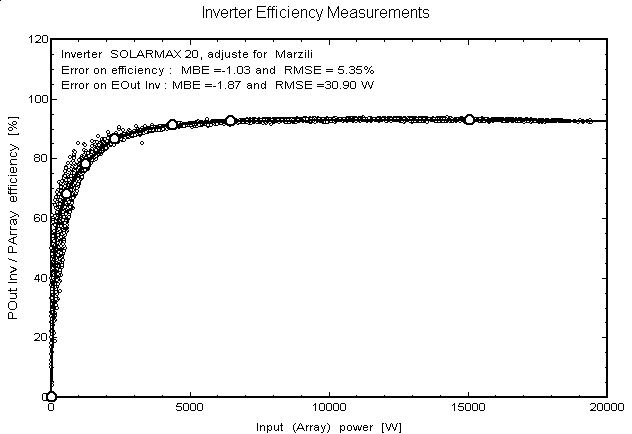
Fig 5b. - Inverter response, after manual adjustment (Marzili).
Conclusion (1996):
With the exception of amorphous collectors, we can assess that the PVsyst software is capable of simulating a large number of different grid-connected systems with excellent accuracy. By independently testing each of the algorithms, we have tried to identify the uncertainties related to measurement and parameter's determination, and those inherent to the modelling. Finally, it can be stated that the accuracy of the global results of the simulation is of the order of 2 to 3% (MBE).
However, the specificity of the PVsyst programme will rather be the detailed and comparative study of special disturbing effects, and in this use, the quality of the different models allow us to hope for much higher precision.
Stand-alone systems, and particularly the battery model, have not been validated up to now. We hope to find properly measured data, recorded in hourly values, to further analyse the software accuracy.