|
<< Click to Display Table of Contents >> U-Value measurement |
  
|
|
<< Click to Display Table of Contents >> U-Value measurement |
  
|
The U-value measurement requires a long-term data acquisition on-site (typically several months with 5-10 min or hourly values), in order to gather data for a sufficient panel of meteorological conditions. This measurement is done on the PV array in operation.
We have to get measurements for:
•The incident irradiance on the collector plane (POA or GlobInc value),
•The ambient temperature (as close as possible of real meteorological data measurements, as the "meteo" data will be used during the simulation),
•The PV array (cell) temperature.
•Possibly the wind velocity (measured in the same conditions as the values which will be used during the simulation).
Then we can draw the distribution of the (Tcell - TAmb) as a function of the irradiance, and evaluate the slope.
With wind velocity measurements, the treatment would be more complex, involving a bilinear fit. We intend to develop a dedicated tool for such analysis in a next version of PVsyst.
Example
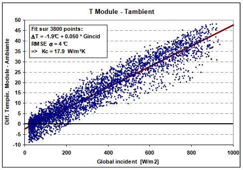
Here is an example of a one-year measurement on a PV array of frameless modules, fixed with a 8 cm gap on a quasi-horizontal steel roof with some spacing between module rows.

The linear regression gives a value of -1.9°C at the intercept GlobInc = 0, and a slope of 0.05 °C / W/m2
From the previous expression:
Ginc · Alpha · (1 - Effic) = U · (Tcell - Tamb)
we easily deduce that the
U = (Alpha * (1-Effic) ) / Slope
| NB: | In this old system, the U-value was named K-value. |
This system was an amorphous system with an average efficiency of the order of 5%
And the slope was accounted without the intercept of -1.9°C, i.e. 0.048 °C/W/m2K.
| NB: | On this graph, we observe temperature differences (Tarray - TAmb) inferior to 0 at low irradiances. |
| This is explained by the Infrared exchange deficit by clear sky conditions. The PV array emits an Infrared radiation according to its temperature. This emission is counterbalanced by the emission of the ambient environment. When the weather is covered, the ambient IR is produced by the close environant air. But under clear sky conditions, the IR is emitted from the high layers of the atmosphere, which are at lower temperatures. This may explain temperature differences of several degrees. |
Array or Cell temperature measurements
The Array temperature is measured with sensors (thermocouples, PT100, or others) usually glued on the backside of the PV module. However this doesn't measure the exact cell temperature, as you have a thermal flux across the cell, the backsheet, the glue, the sensor and finally the air. The temperature drift between the cell and the sensor depends on the relative heat resistances of these layers.
For getting rid of this heat flux, we can cover the sensor by some insulation. This insulation should not be too big, for avoiding a too high perturbation of the PV module temperature. We should find a compromise between these two constraints. At the University of Geneva, a diploma work compared the measured temperature with different insulations, with a reference sensor directly positioned on the back of a cell, within the encapsulation. This optimization lead to a sensor glued or fixed with thermal grease, covered by an insulation of a polystyrene piece of 1 cm thick, and 7 x 7 cm2. Note that in practice this polystyrene piece should be mechanically fixed from the frame of the module, as the glue or adhesives usually don't resist to high temperatures.
| NB: | Some people propose to add 3°C to the rear-side measured temperature for taking into account the temperature drop due to a heat flux from the Cell to the sensor. |
| This would be valid if the sensor is not recovered by an insulation. In this case we don't know what is really measured by the sensor: an intermediate temperature highly depending on the ratio between the heat resistance in the rear sheet, and the sensor with respect to the ambient. Moreover the difference between cell and sensor is obviously proportional to the heat flux, i.e. the (TArray-TAmb) temperature. Therefore we can't understand this fixed correction of 3°C. |