|
<< Click to Display Table of Contents >> Use case : Complex PVsyst scene |
  
|
|
<< Click to Display Table of Contents >> Use case : Complex PVsyst scene |
  
|
In this use case, we're going to see how we can manually group fields together in a complex scene, after we imported it from a DAE file we built in Sketchup.
There are three distinct zones of fields placed on a hill, each zone has a unique nominal tilt/azimuth pair. All fields follow the terrain slope so their normal vectors are varying.
We define the three nominal orientations which we expect to get, they are the ones we defined when we created the scene in the other software.
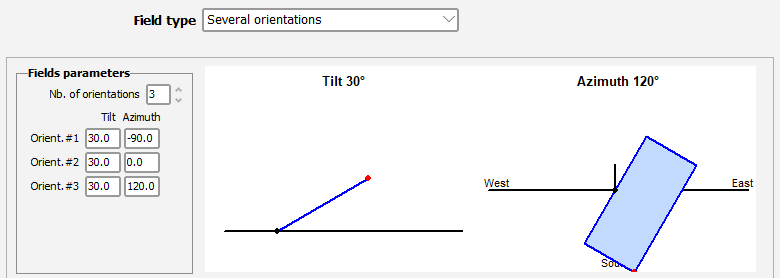
We create three sub-arrays in the system, one linked to each orientation, and we set the expected area of each zone.


Here is the scene after we imported it in PVsyst :
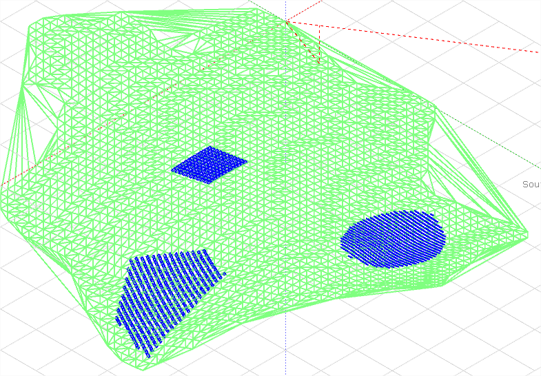
We can clearly see the three zones
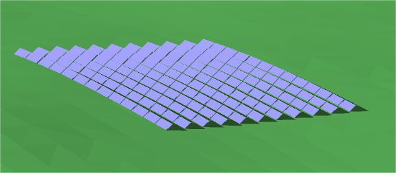
This shows how fields follow the ground slope
Now let's open the orientations management window to see how they are grouped by default.
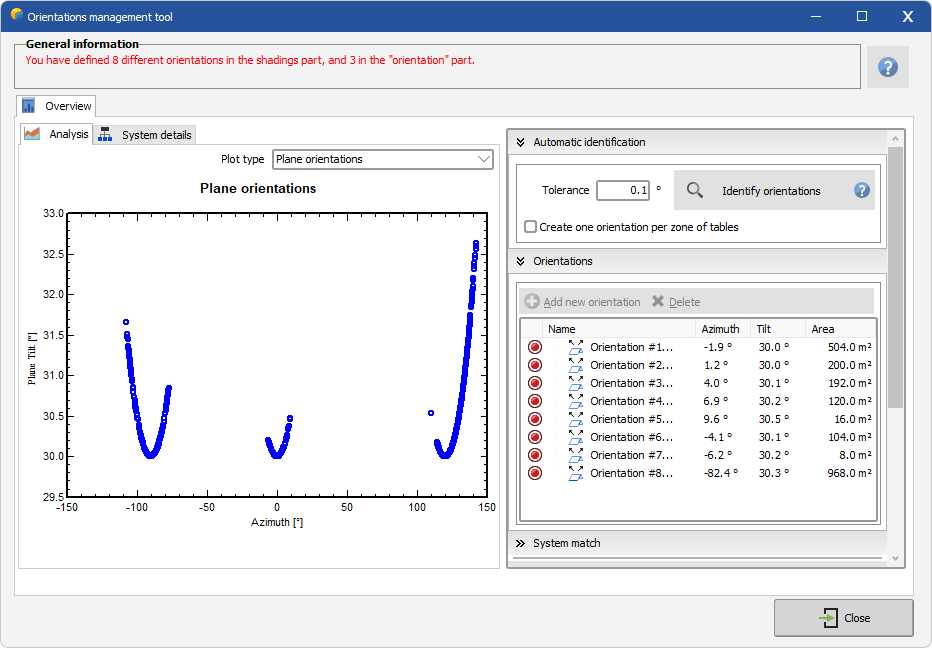
We can see that fields are grouped automatically in 8 orientations with an angle tolerance of 1°, which is not want we want.
We could try to increase the tolerance but it would not be accurate and we have no guarantee that it would group fields perfectly in the end.
So we are going to define our three orientations manually.
Step 1 : Deleting orientations
We select each orientation and delete it until there is no automatic definition left.

Step 2 : Creating the three orientations
We will create the orientations directly from the shading scene selected objects, this way it will be easier to make sure that the good fields go in the good orientation.
Let's start with the first zone (azimuth = -90°), we select the fields using the lasso selection tool in the scene.
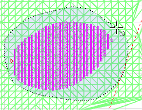
When the fields are selected, we right-click on one of them in the right-panel and select Create orientation from selection
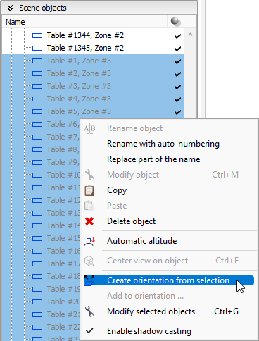
And now the orientation appears in the management dialog :

We notice that it has the correct area and close but different tilt/azimuth, due to the average calculations.
Now we repeat it for the two other orientations and get this result :

We open the System match tab to confirm that orientations don't match due to the averages being a bit different.

We know that we have it all well defined, and we want to use these shadings definitions in the variant so we click on the button to update them.

The orientation definition is now over, we have a valid system and a valid shading scene so we are able to perform simulations.
In this example we knew the area of each zone so we created the System accordingly, but if you don't know them exactly just do the same and you will be warned at the end that areas don't match.
Just go back to the System part to adjust it with the values given by the orientations dialog and everything will match.