|
<< Click to Display Table of Contents >> Use case : Checking scene validity |
  
|
|
<< Click to Display Table of Contents >> Use case : Checking scene validity |
  
|
In this use case, we're going to see how we can interpret the matching errors and get an orientations definition to match the variant one.
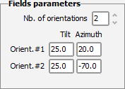
Two fixed orientations

One sub-array of 50m² linked to orientation #1

One sub-array of 50m² linked to orientation #2
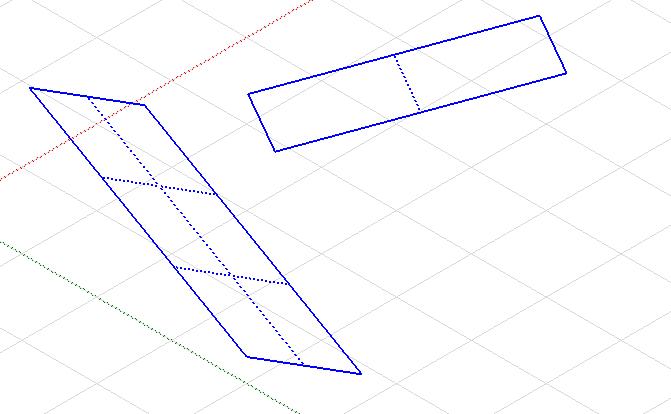
Two rectangular fields, one of 50m² and another of 160m²
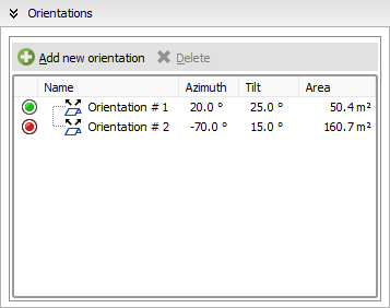
One field is 20/25° (azim./tilt) and the other one is -70/15°
We can see that the second orientation found in the shadings is marked with a red icon, when the first one is green. This means that it is not matching the system correctly and needs some adjustments.
Let's open the System match panel :

It says that is just has no match in the System, which means that we have two solutions:
•update the System definition from here
•edit the field causing the error and change its tilt to 25°
We'll go for the second one and edit the field's parameters, now the orientations look like this:
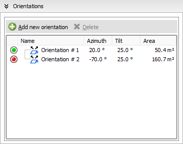
The orientation #2 has now the correct tilt and azimuth definition but it is still marked as red, so we check the System match panel :

The error message is clear : the active PV area is too large in our shading scene, we need to decrease it until we get close to 49m².
After decreasing the field size, it's area is now 46.7m² and the orientations dialog shows this :
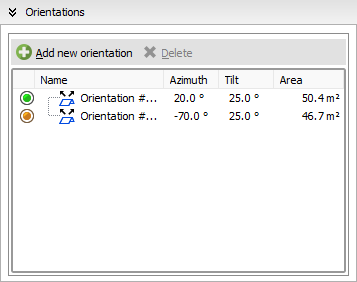

It is only showing a orange warning which means that this is not blocking for the simulation, the area is respecting the tolerance so it is possible to go on with it.
The orientation #1 area is really close to the System one so it is displayed in green and considered fully matching.
Depending on how you design your systems, you will sometimes need to consider the shadings definitions like the good ones and override the variant definitions. Or, you will follow the error messages to get your shading scene to match the variant.
As long as you have no red error messages while checking the match, you will be able to perform the simulation.