|
<< Click to Display Table of Contents >> Power Factor |
  
|
|
<< Click to Display Table of Contents >> Power Factor |
  
|
Basic definitions:
In an AC circuit, the Power (or Energy when integraed in the time) may be described by:
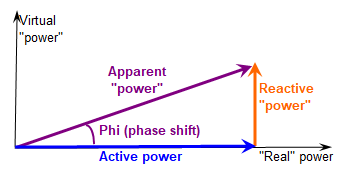
•Active Power: this is a real power, able to create movement or heat.
•Reactive power: virtual "power", created or absorbed by devices like inductors (motors) or capacitors.
•Apparent power: is the combination of these contributions.
In a sinusoïdal evolution, these contributions are a result of the phase shift of the current with respect to the voltage.
These quantities are usually represented on a vector diagram:

In an AC circuit, the apparent power is defined as the product of the voltage by the current, when these are measured independently (i.e. the effective value of the voltage and the effective value of the current); Papparent = Ueff * Ieff, expressed in [kVA].
The active power is the power obtained along one sinus period, when we integrate the product of the instantaneous Voltage by the Instantaneous Current at each time step. This results in a multiplication by the cosine of the phase shift:
Pactive = Ueff * Ieff * Cos(phi) expressed in [kW].
The reactive power is the vectorial difference of these contributions:
Preactive = Ueff * Ieff * Sin(phi) expressed in [kVAr].
We name "Power factor" the ratio between active and apparent power, i.e. Cos(phi).
It is very important to observe that the "Reactive power" is not a real power (not an energy): it cannot produce any movement nor heat nor any other effect.
Reciprocally, you can create Reactive power without consuming any "real" (active) power. This is what happens in capacitors or inductors.
NB: The Cos(Phi) value defines indistinctly the Leading and Lagging situations. People sometimes use the Tan(Phi) quantity for distinguishing between these situations.This is not really significant in PVsyst, as we only deal with the active energy. .
Reactive power produced by an inverter
The active energy produced by an inverter is always a result of the input DC energy provided by the PV array. Any "real" energy difference between the output and the input of the inverter would be transformed into heat (this is the case of the inverter's inefficiency).
Now with the new technologies (PWM) it is possible to create voltage and current signals with any phase shift, at no additional energetic cost. This is just a question of programming in the PWM control.
This is the reason why the grid manager may ask the PV systems for producing Reactive energy, in order to compensate the reactive energy consumed by the motors (and other devices like switching power supplies). Otherwise this is ordinary done with big sets of capacitors.
This phase shift production results of an explicit control within the inverter, i.e. a parameter specified by the control system. In PVsyst we consider fixing a constant Power factor along the year, or possibly in monthly values. Specifying this in hourly values is foreseen, but not yet implemented.
In the simulation results:
The energy E_grid calculated by the PVsyst simulation is the active (or real) energy, expressed in [kWh].
When defining a Power factor, the results will define a new quantity, the Apparent Energy:
E_GridApp [kVAh] = E_Grid [kWh] / Cos(Phi)
This result will appear at the bottom of the loss diagram.
The apparent energy is obviously always superior to the active energy.
Effect on PNom
The inverter production is basically independent on the Power factor.
However there may be an effect on the overload conditions, according to the inverter's specifications.
▪either the nominal power PNom is specified in active power [kW]. In this case the simulation is not dependent on the Power factor.
▪or the nominal power PNom is specified as apparent power [kVA], so that the power limitation will occur for an active power PNom(act)[kW] = PNom(app)[kVA] * Cos(Phi). As the Pnom8limit) is lower, the overload loss will be higher, and depends on the specified Cos(Phi).
NB: Since the version 7.3.3, each inverter operates according to its own Pnom mode specification. There is a possibility of forcing all the inverters in one or the other mode, but this is not recommended. This should only be used for tests.
Effect on Grid limitation
The same situation arises for the grid limitation. The grid manager may ask for a limitation in apparent or in active power.
NB: some grid limitation requirements are based on a specific state of the Grid (especially the grid voltage). Taking such requirements into account is not possible in a PVsyst simulation, as it would require knowing the Grid voltage at each time step, as an input parameter.
Effect on the AC losses
When applying a power factor, for keeping the same active power, the current has to increase:
Ieff (apparent) = Ieff (active) / Cos(phi).
Therefore the wiring ohmic losses - proportional to I² - will increase, either in the wires, and in the transformers.
NB: In the present time, PVsyst doesn't evaluate the impedance losses, especially in the transformers. Therefore the reactive energy is identical at the inverter output and the injection point. i.e. the Cos(phi) specified in the inverter is equal to the value required at th grid level.
Procedure
The operating power factor is specified for the whole system. You define it using the "Energy Management" button.
The power factor may be specified in yearly or monthly values. .
For grid limitation, you should choose whether the limit is in active or in apparent power.
NB: The derogation options "Force as apparent/active power" will force all inverters to operate under this conditions. This has been kept here for compatibility with old versions < 7.3.3, and for possible tests. It is not recommended.