|
<< Click to Display Table of Contents >> Wiring loss optimisation |
  
|
|
<< Click to Display Table of Contents >> Wiring loss optimisation |
  
|
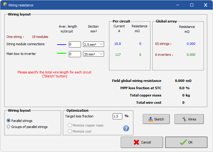
The aim of this tool is to choose and optimize the wire diameters in the array, given a predefined loss limit. This will also calculate the full equivalent resistance of the Subarray, to be used in the simulation.
For the calculation principles of the equivalent resistance, see Array Ohmic Wiring Loss
Wiring schema
First give a look on the array usual wiring schema, by pressing the "Schema" button. This identifies the different parts of the circuits by colors:
- The "string" connections between all modules of a string, up to the wiring connection box (usually situated near the array).
- The connection between this boxes and the system (inverter, battery, …),
- Optionally, when choosing "Groups of parallel string", the connection between the group boxes and eventual combining boxes.
Define the wires
Secondly, you have to specify the average wire length for each circuit category (average full length of each circuit, i.e. from minus to plus poles for each loop).

The program shows the nominal current and the resistance of one branch, as well as their contribution to the whole array resistance (as seen from the array connections). It proposes a list of standardized wire sections, beginning from the smallest wire compatible with the actual loop current.
The "wire" button allows to see the standard wire properties (diameters, maximum current, resistivity), as well as eventually their price, which you can define in order to optimize the wiring cost. The maximum wire currents are given by the European Norm, for isolated wires mounted in apparent or ventilated mounting ducts (CEI 364-5-523, 1983)
Finally, you can specify a maximum loss:
| - | either in terms of % (at MPP) when operating at MPP, |
| - | or as a voltage drop when operating at fixed voltage. |
The program will then optimize the wire sections matching these requirements, either minimizing the copper mass, or the wiring cost provided you have defined the wire prices in the "wire" dialog.